Archive
DIYINHK Isolated XMOS USB Interface
DIYINHK has developed a new version of the XMOS-based USB to I2S Audio Interface. This version provides isolated I2S signal lines. Plus it uses superior oscillators.
You can read about the older version here [link]


ISOLATOR
The Isolator chip is the Silicon Labs 8661 Low Power 6-Channel Digital Isolator [link]. This is the newest device from Silicon Labs. It is based on RF coupling [link]. Apparently the Si-Labs isolators are the lowest cost ones [link]

Si86xx enhancements include:
- Schmitt-triggered inputs for higher input noise immunity
- Increased ESD protection
- High noise rejection linear regulators to ensure quiet bias voltage
- Lower power oscillators for greater operating efficiency and faster output buffers with tightened 50Ω source impedance for better matching
- Compared to competing digital isolators, Si86xx products provide near zero EMI emissions
- Industry’s highest data rate (150 Mbps) across the widest temperature range (-40 to 125 ºC) and low power operation of <1.6 mA per channel at 1 Mbps.
The “clean” side of the isolator requires a separate power supply which must be provided for proper functioning. You need to provide a 5-16V supply. This will be further regulated by a low noise regulator.

OSCILLATORS
According to DIYINHK, this version uses NDK NZ2520SD Ultralow phase noise oscillators from Japan. There are 3 oscillators: the 48 MHz for the digital circuitry of the XMOS device, the 45.158MHz and 49.152 MHz for the audio frequencies.


NDK has some general information on their oscillators, including jitter data here: [link]. Below is the phase noise plot of the NDK oscillators. Note the phase noise curve of the “SD” models.

NDK’s NZ2520SD low-phase-noise crystal oscillator has phase noise characteristics superior to those of the general NZ2520SB model. The company’s high-accuracy crystal oscillator (OCXO) has even better phase noise characteristics near the reference frequency.
Here is the phase noise plot of the Xpresso oscillators used in the previous version

And here is the phase noise plot of the CCHD-957. Note the phase noise value of the CCHD-957 at 10 Hz (-97) vs the phase noise value of the NDK oscillator at 10 HZ (-113)

MASTER CLOCK
The Master Clock is available straight from the NDK oscillators or at the appropriate scaled-down frequency through the output pins.
Straight from the oscillators (45.158MHz and 49.152 MHz) through a U.FL socket:

Through the output pins (22.5792Mhz/24.576Mhz).
The “C7424Z” device is used as a clock divider to generate the 22.xx and 24.xx frequencies used by XMOS device and also used by the downstream device (the DAC). Seems the clock line to the XMOS device is also isolated in order to prevent any kind of noise leakage from the XMOS/USB side to the Clock/Clean side.

Note that there is no “re-clocking” of any of the I2S signals. However, Xout can be used to control an external re-clocking board for the I2S lines.
COMPLETE ISOLATION
As we’ve seen, the “clock section” including the I2S signal lines is isolated from the “XMOS/USB section”. The master clock line generated by the local clocks that connects to the XMOS device is also isolated. The two sections are powered independently.
On the backside of the board, we can see that the ground planes are also separated between the “clean side” and the “dirty side”:

USB POWER
The XMOS side (or “dirty side”) is powered by USB by default. Just like in the earlier version, the USB power can be bypassed by removing the FB1 ferrite and external 5V power can be applied through the external power connectors.

REPROGRAMABLE
For the advanced DIY’er, the XMOS device can be reprogrammed with different firmware. This can be accomplished through the CN6 connector (which is the JTAG interface for the XMOS chip):

The following device from XMOS, the xTAG-2 [link] can used to upload new firmware to the XMOS device (updating firmware through USB is not enabled in the default firmware). The xTAG-2 provides a high speed, low latency bridge between USB on the host and fast JTAG connection (up to 10Mbps) on the target.
JTAG enables the transfer of data into non-volatile device memory (uploading firmware).

There are 20 pins in this device because the device is also a debugger. The JTAG interface pins are specified in the hardware manual [link]
C-Media CM6631A Firmware Tool
While testing a CM6631A interface, I discovered that for 44.1K/48K sample rate material, the bitclock was running at 128FS (rather than the more common 64FS). Thus when connected to a Sabre 32 DAC, it reported a sample rate of 88.1K/96K. I described the behavior as “2X bitclock” [link].
2X BITCLOCK
BLCK is the same for both 44/48K and 88/96K. This means that for 44/48K sample rate, the data is running at 128fs and for the rest of the sample rates, it is running at 64fs.
Even though the Sabre32 DAC specifies BCLK to be 64 fs, it appears that it also supports 128fs. Why? because when I play 44.1KHz material, the DAC reports 88.2KHz sample rate and it sounds perfectly fine. (The sample rate reported by the Sabre32 DAC is based on the frequency of the bitclock, the DAC reports 88.2KHz for 44.1K material)
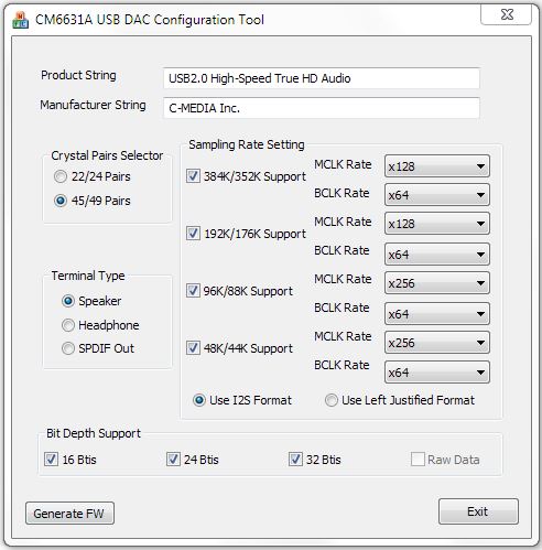
C-Media, announced the availability of a firmware tool that allows the selection of the bitclock frequency and other parameters [link]

It creates a hex file when you click “Generate FW”. The destination folder must be the folder where the file “UsbDac.bin” (which comes with the config tool) is located

In order to “fix” the “2X bit clock” issue, you need to select x64 BLCK. For the DIYinhk board, you also need to select “Speaker” for Terminal Type and “I2S Format”
Then you need the “Firmware update tool” to upload the s/w to the CM6631A-based interface.

There is instructions included with the FWUpdate tool. If you need a copy, you can ask user tdtsai at diyaudio [link]
Once you update the FW with the x64 BCLK rate, the 44.1K/48K sample rate will correctly display in the Sabre32 DAC.
Diyinhk has a new version of this board that also takes advantage of the config tool to generate different versions of the firmware [link]
- The board has two I2S output is available. The diyer can flash the firmware and enable “Headphone I2S” (non-isolated) and “Speaker I2S” (isolated) if needed.
- The SPDIF (coaxial /optical) connection is routed out for diyer to mod (tap) if needed
Apple Airport Express USB Audio Output Mod
The Airport Express is Stereophile 2014 recommended component [link]:
Apple AirPort Express: $99 $$$ ✩
While the Airport Express works only with iTunes v4.6 or later (running on both PCs and Macs), is limited to 16-bit data, and functions only at a 44.1kHz sample rate, the combination of iTunes and the Airport Express offered an easy way to pipe CD-quality music around the entire home. “The beauty of this unassuming component,” said JA, “is its S/PDIF data output, which allows the Airport Express to assume a respectable role in a true high-end audio system.” However, its lack of an internal clock can lead to the first couple of seconds of songs being missed with DACs that are slow to lift their mutes.
Its performance can be enhanced several notches if the I2S digital output can be tapped.
I have been contemplating modding the Airport Express since at least 2009 [link], but never got around doing it.
Now, adding an additional “Airplay” input to the audio system is a desirable option, especially for an “iOS household” like mine. With multiple built-in switchable inputs available in the Sabre-32 DACs which are easily implementable under software control [link], there is even no need for an external switching device.
Certainly no modding is necessary since the AE already has a Toslink output. But for diyers, there is always something to mod 🙂
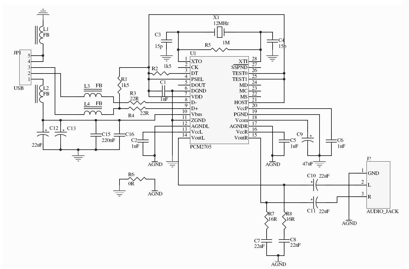
I2S Output?
For this model of AE, tapping into the I2S signals is not feasible since it is based on the PCM2705 which only supports SPDIF output. (for I2S output, you would need a different PCM chip (PCM2706 or PCM2707) or use a newer version of Airport Express that uses an I2S based DAC such as the second and third generation AE (the first generation “N” and second generation “N”. The original was 802.11 “G”).
Best Model for Audio?
Reports seem to indicate that the original AE is probably the best one to use for audio and for modding…
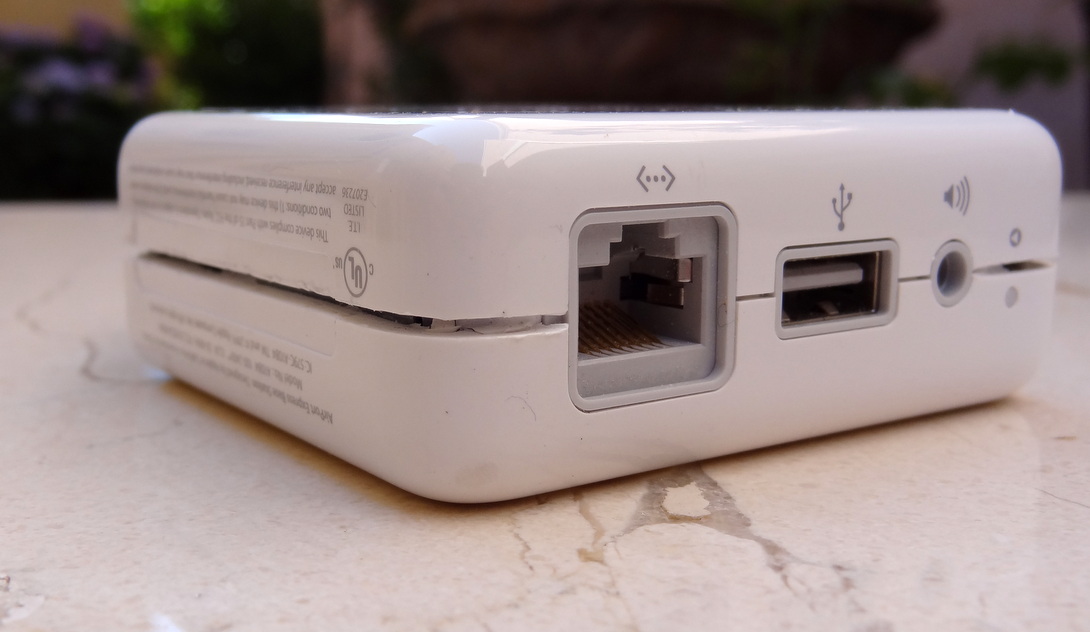
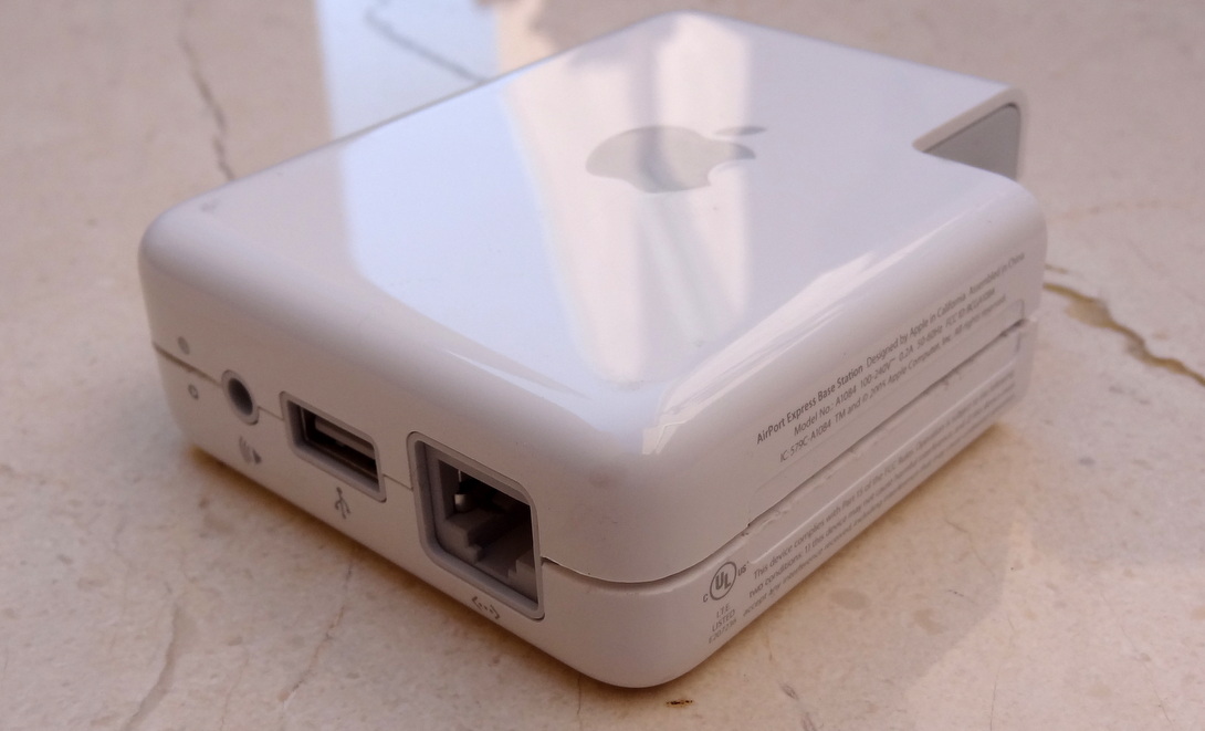
The original Apple Airport Express was introduced in 2004. According to Wikipedia,
The original version (M9470LL/A, model A1084) was introduced by Apple on June 7, 2004, and includes an analog–optical audio mini-jack output, a USB port for remote printing or charging the iPod (iPod Shuffle only), and a single Ethernet port. The USB port cannot be used to connect a hard disk or other storage device.
The original AE (“G” version as in 802.11g) seems to have the “best” audio performance of all the AE models.
1- Tests published at CA shows that the “First Gen N” version (the follow-on version to the “G” version) has better audio than the current “Second Gen N” version of AE [link]
…To make a long story short, yes, the AE First Gen will have a lower jitter and better sound with your outboard DAC, than the AE Second Gen. An outboard DAC can only suppress incoming jitter, but can never remove.
2- The “G” version in turn has better audio performance than the “First Gen N” version of AE:
I have both a wireless G model & a wireless N model. My DacMagic frequently lost lock when used with the N but is rock solid with the G. At the time I was struggling with this issue, forums and such indicated that the jitter in the N model was much higher than the G…
OPENING THE AIRPORT EXPRESS
For reference here is the “original” Airport Express take-apart post: [link]
The two halves of the Airport Express are bonded together with some kind of crazy glue. The only option is to cut it apart. But rather than brute force, I preferred an approach with some finesse…:
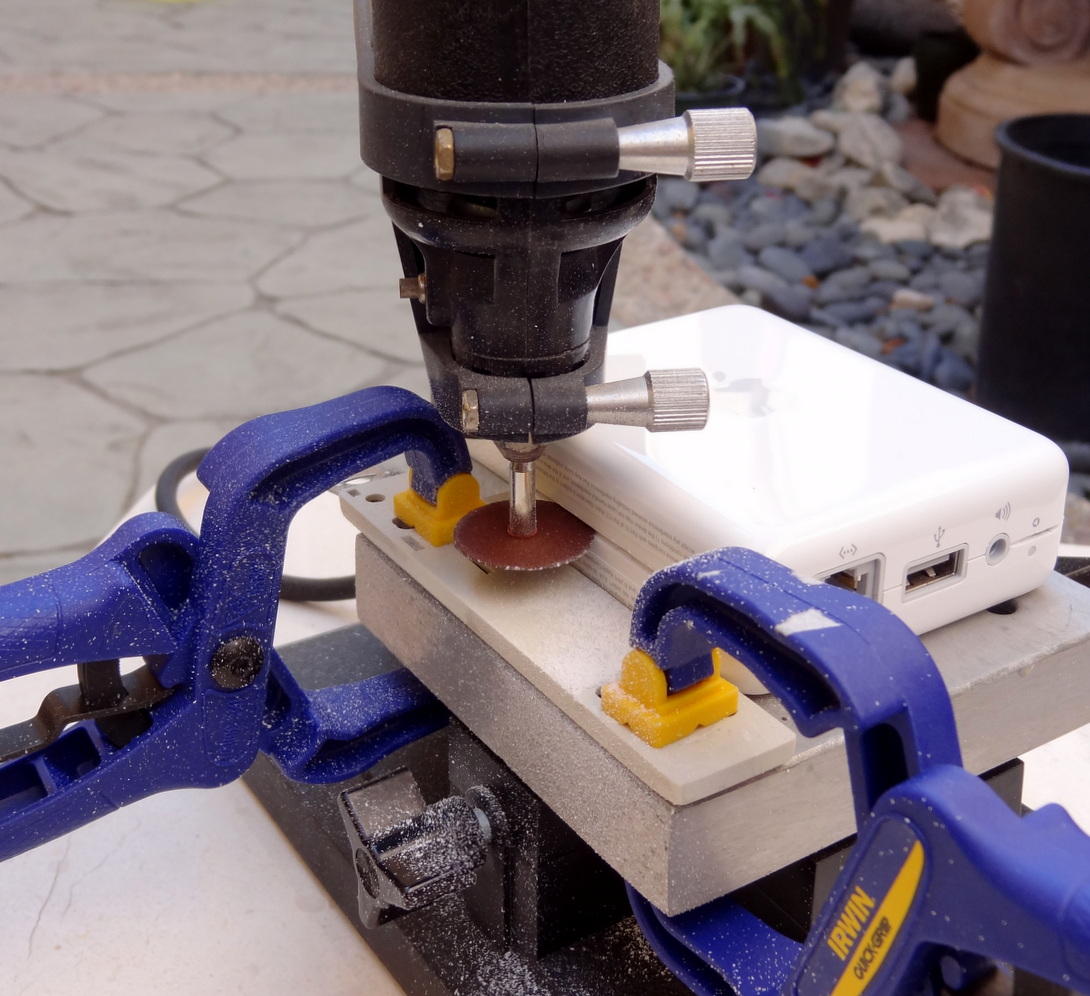
Several passes were required in order to gauge the appropriate depth and avoid cutting into any internal components. In particular the power supply wires are butting against the casing.


The case can still be used after cutting the the case apart. Apple is a master in industrial design. We’ll try to save the case.
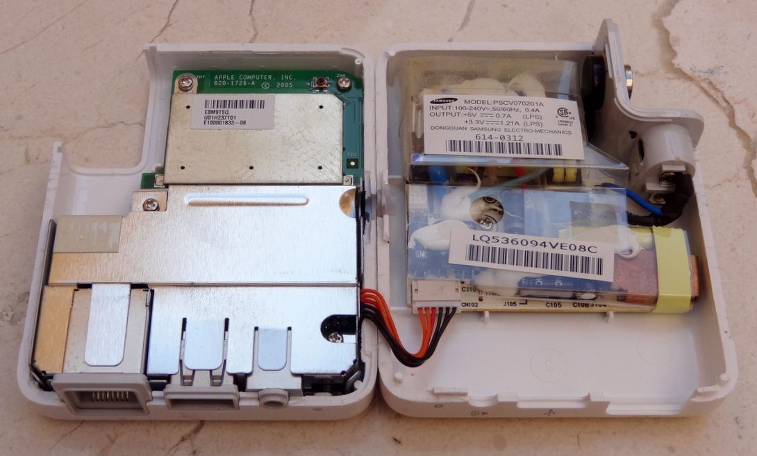
Inside the Airport Express.

Certainly a cleaner approach than what iFixit did 🙂 [link]


The switching supply was made by Samsung in their China Dongguan factory (Dongguan is about an hour drive from ShenZhen). Nowadays, Samsung is likely not building “low-end” components anymore…

THE AUDIO BOARD
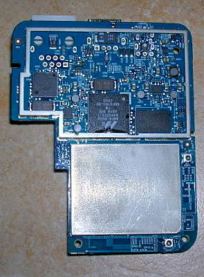
The AE is partitioned into two parts: the network board and the audio board. The audio board is a daughter card that plugs into the network board.
Removing the RF shield:

Removing the audio board:

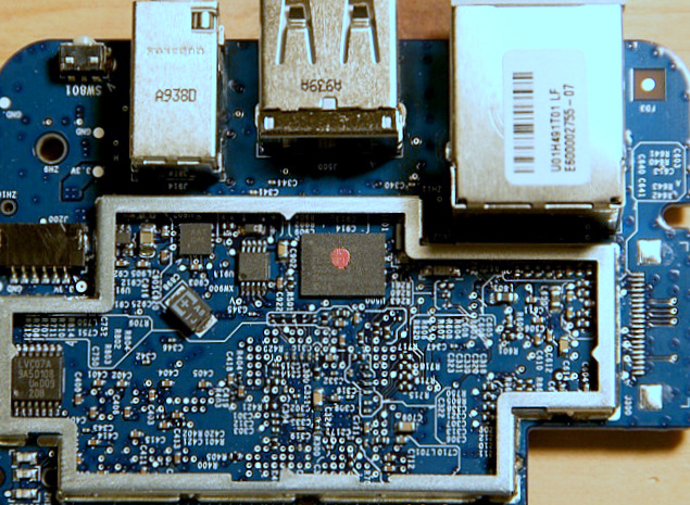
The audio board in detail. Even for a simple DAC implementation such as this, the board is a 4-layer PCB.


The PCM2705 USB DAC

NETWORK BOARD


That is a lot of electronics in a $99 package!
COMPARING WITH OTHER AE
Here is the 2nd Generation (also knows as the first generation “N”) AE. This version connects to the on-board DAC chip with I2S

The DAC chip used in the second generation AE is the CS4344 (the 10-pin chip in the photo below)
Here is the 3rd generation AE (current generation) courtesy of Rogue Amoeba
SOME EXPERIMENTS
Functionality without the audio board
I tried powered up the AE without the audio board in place. It turned out that the networking capabilities of the device work fine, but its Airplay capabilities were disabled. Seems the AE performs a power-on self-test and disables the Airplay capability if it finds the audio section not functioning.
PS Wiring
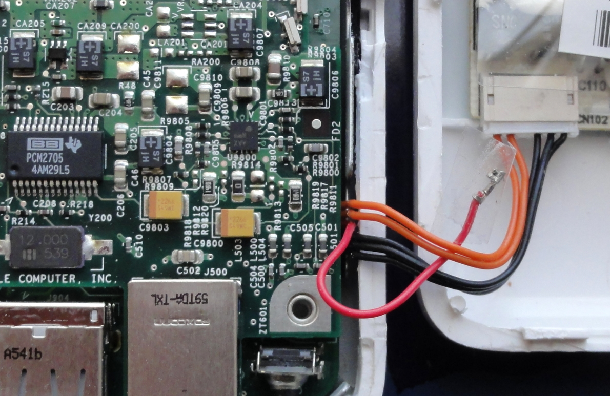
According to iFixit, [link] the 3.3v and 5v supply wires are as follows:
- Black wires: ground. All three should be connected to the two ground wires from the power supplies.
- Red wire (middle): 5V, 0.7A power input.
- Orange wires (two on the right): 3.3V, 1.21A power input.
Functionality without the 5V supply
I removed the red wire from the connector to test whether the device would operate without 5V. (If this is the case, then replacing the power supply would be easier since we would only have to worry about a single supply -the newer AE only require 3.3v for operation)
Result:
The network part of AE works without the 5V supply. Now, lets see if putting back the audio board will enable Airplay… Airplay does not work without the 5V supply.
WHAT TO MOD?
Power supply replacement
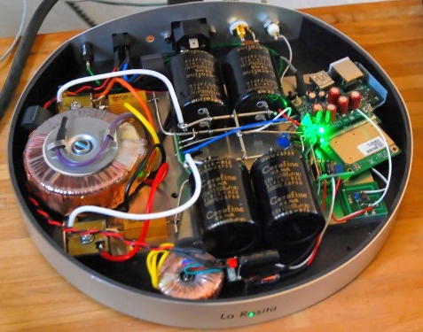
The standard mod has been the power supply mod, replacing the switching dual supply with a linear dual supply. It is the most popular mod on the AE. In fact, there are commercial versions Apple Express with vastly enhanced power supplies such as La Rosita Alphas:

…and the Micromega Streamer products:


Notice the unique design of the Micromega: the antenna of the AE extends outside of the case for better reception (I suppose if you totally enclose the AE the WIFI reception would be very poor)
“MONSTER MOD”
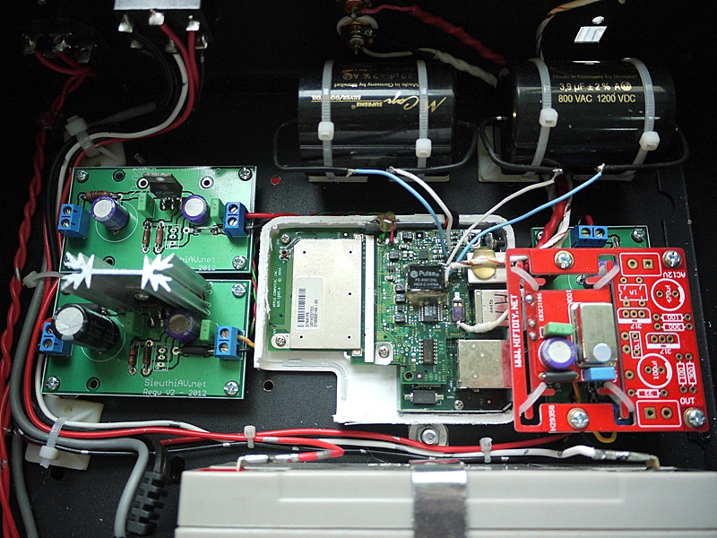
I found this project in the Vietnam AV Network. The user replaced the clock, power supplies, and output capacitors, plus a isolation transformer in the spdif output [link]
USB AUDIO OUTPUT MOD
I have not seen another reference to this mod. So I think it is the first 🙂
What if we can take the USB output, and feed it to an external USB interface? We can then try different devices such as the PCM2706 with both SPDIF and I2S output, or the TENOR TE7022 with similar capabilities. We can add isolation. Isolating the USB will greatly clean up the digital signal and isolate the more sensitive audio part from any digital noise in the AE, including noise generated by the network/wifi chips and related parts.
No need to replace the original PS?
Since we tapping into the USB Audio stream, a purely digital signal, there may be not much to gain in replacing the original PS, especially since we can later add a USB isolator for full isolation. In addition, being a communication device, we can be assured that the designers have done their work in ensuring no (at least unrecoverable) errors in the digital domain.
Undoubtedly, a PS mod would benefit the analog performance and even perhaps the conversion to digital audio, but for this mod, I think am going to leave the original PS in place.
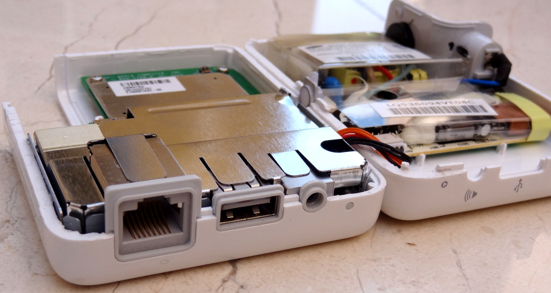
Looking closely to the input power connector, we can see that the designers have taken good care in filtering out the noise from the switching supply. Aside from the EMI shield covering the components, we find that the power lines and ground are further isolated with ferrites:

Tapping to the USB lines
The USB data from the AE audio board is “readily available”. There are 4 vias where the the 4 USB signals can be tapped:

We can even leverage the built-in USB connector by first cutting the existing lines (which are only good for connecting to a printer) and tapping the USB signal from the Audio board. 5V and GND are already there, so only two wires are needed:

Here is the mod. I tried to move the wires away from any active circuitry. Zero cost and completely and easily reversible.


Cut the original signals to the USB connector (which we won’t use anymore since this is for printer sharing)

The metal shield covers everything including the USB wires

TESTING THE MOD
I used the iBasso D2 USB Portable DAC/AMP to test my mod. The USB interface is the PCM2706 and connects to the Wolfson WM8740 DAC. The PCM 2706 is part of the PCM 270x family, so it should work…
Results:
Airplay complains that there are no speaker connected to the AE. The device is just too smart. It senses if there is a plug in the output connector and prevents Airplay from connecting if there is nothing plugged in… No problem. Use any mini-plug into the output port.
Now Airport connects, I first try to to connect a portable speaker to ensure that everything is in working order. I get sound in the speaker…So far so good.
Now I connect the iBasso into the USB port of the AE… Nothing… The iBasso has a “link” LED and it is not lit. No connection to the iBasso…
OK, perhaps I need to reboot the AE with the iBasso connected… Reboot… Airplay does not show up in iTunes… This AE is just too smart. I figure that since there are two USB interfaces connected, the AE can’t figure out what is going on (there is no handshake/link to any of the two DAC chips) then the self test fails and the AE does export itself as a functional device…
Back to bench.
I theorize that the firmware in the AE is looking to one USB DAC to link up with. I would make sense to turn off the on-board DAC chip and allow a single device to hang off the “USB port”.
Pin 7 is the VDD (digital power) for the PCM2705. We can just lift the pin.

I didn’t even have to use the soldering iron. Just an exacto knife and a bit of pressure. There is also analog power, but I won’t bother lifting those.
Result: Yes! it works. After booting up the AE with the iBasso connected, immediately the link LED lights up. Airplay shows up in iTunes… Play a song… Ahhh… Music!

UPDATE (July, 2015)
SAVIAUDIO SA9023/SA9027
Recently, low cost DACs and USB-I2S interfaces have been implementing with a new device: The SaviAudio SA9023/SA9027 [link]. No device driver is needed under Windows implying that it is compatible with USB 1.1 sound, the same as the PCM 2706 of the Airport Express.
The Teradak is a USB-I2S board using the SA9023. The chip is advertised to have jitter <100 psec. [link]


The HifimeDIY Sabre USB DAC has been updated with the SA9023 [link]. According to the specifications, no driver is required for Windows.
- Supports 32khz, 44.1khz, 48khz, 88.2khz, 96khz and 16 and 24 bits
- Works in USB Adaptive Isochronous mode (same as PCM2706)

The SA9023 USB interface chip can also be implemented as “Asynchronous mode” [link]
Notice a second 27MHz clock in addition to the 12 MHz clock. I am not sure if this configuration would work with the modded Airport Express.

The all digital amplifier SMSL Q5 uses the SA9027 for USB input. Since there is a single clock near the USB circuitry (upper right corner), it would be safe to assume that it is operating in Adaptive mode.
The SA9027 adds 32-bit support


I had a chance to try this device with the modded Airport Express. Sadly, it is not compatible. I does not recognize this device when connected to the USB port. I have not have a chance to try the SA9023 USB.
CM6631A 384KHz
Took advantage of the new beta firmware for 384K support [link] and tried in the diyinhk CM6631A USB interface.
According to tdtsai,
CM6631 do not have this capability to support 384k/352.8K. So we can’t change firmware to support it. By the way if you want CM6631A to support 384k/352.8K you need use 45/49 pairs external clock.
The diyinhk interface has both the CM6631A chip and also the higher speed clock pair.
UPDATING FIRMWARE
I received both firmware and update tool from Mr. tdtsai (see the diyaudio link above)
Current firmware

New Firmware

To play 384KHz material I used quanghao’s DAC (since it requires 100 MHz clock and my Buffalo DAC has an 80 MHz clock)
BTW, users have started to receive the “production” model of the group buy [link]
RESULTS
Well, it plays as advertised. More and more interfaces are moving up the sample rate capability…
Tried both ASIO and WASAPI. Here is the WASAPI setting in foobar:

Here is the ASIO setting in foobar:

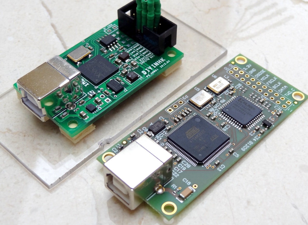
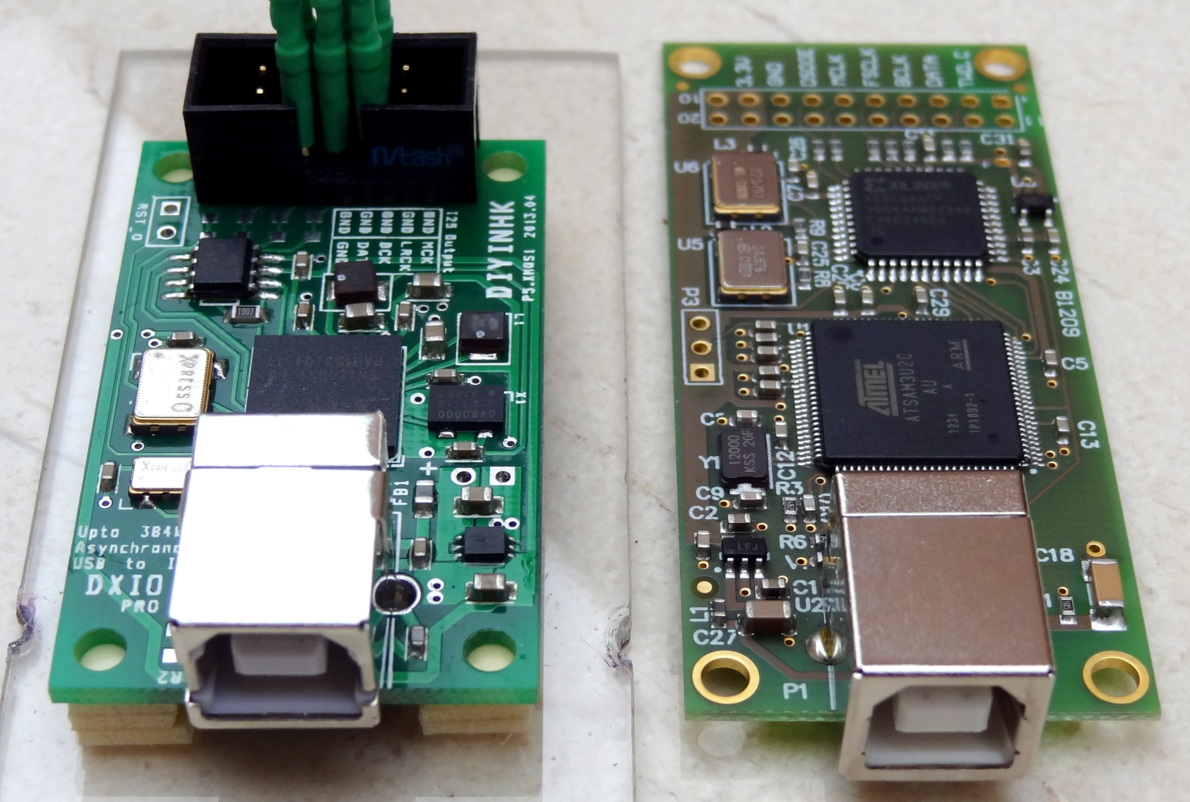
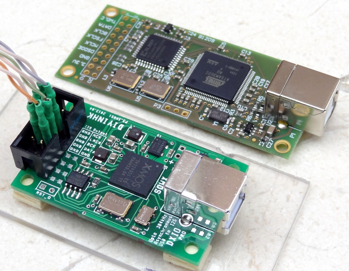
USB-I2S Audio-Interfaces
It is a great time to be an audio diy’er. There is currently great availability of quality boards aiming at providing the greatest fidelity with incredible VALUE.
Here are some side by side photos of the two USB-I2S interfaces I own.

Worthy of mention is the upcoming next generation Wave IO board. Mr. Lorien posted a sneak peek at his next generation board [link]

From the look of the layout, this board has electrical isolation of the outputs and flip-flop reclocking after the isolator.
TEAC USB Interface
Updated 4/30/13
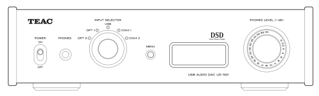
The new Teac UD-501 DSD capable DAC has received good reviews everywhere. Was curious about its USB interface. Here is a photo taken from a French site, qobuz.com [link]

There is a TMS320 chip and an unidentified chip. It is possible the unidentified chip is the USB receiver or the TMS320 is doing receiver function and the unidentified chip is a microprocessor to control the TMS320 chip.
The TMS320 is a DSP chip [link]. It is a “C67” series, an up to 1GFLOP 32-bit floating point DSP (the XMOS are rated at 500-1500 MIPS, likely equivalent performance). This family of DSP products was introduced in 1983 and new models have been introduced along the way.
The “C67” series is a current product and an EVAL kit, in particular for the C6748 chip, is available from TI [link], [link]. According to the documentation:
…The
TMS320C6748, a low-power dual-core applications processor based on a fixed-point C64x+™ instruction set and the floating-point C67x+™ instruction set. It provides significantly lower power than other members of the TMS320C6000™ platform of DSPs and provides both floating-point precision and fixed-point performance in the same device. With a wide variety of standard interfaces for connectivity and storage, the C6748 development kit enables developers to easily bring audio, video and other signals onto the board.… Included in the C6748 development kit is all the hardware and software needed for two demonstrations, a fingerprint-recognition demo and a face-detection demo.
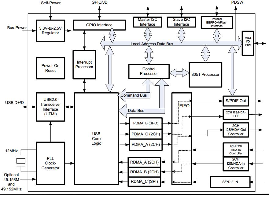
Here is the block diagram for the eval kit:
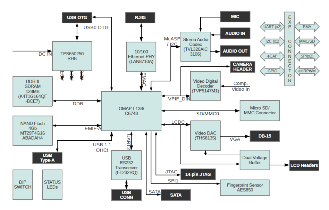
Looks like a very capable and general purpose processor for not just audio but a lot of other things not even related to audio. You can take a look at the WIKI for all the available libraries for the DSP [link]. The DSP can even implement audio decoding and filtering.
In addition, the USB-2 interface is provided by the FT232 chip (and thus the unidentified chip is likely not the USB interface chip; however, there are no FT232 chips in 48-pin package).
Further, the DAC has an upsampling feature and is provided by the Cirrus CS8422 chip on the main taking the I2S output from the USB board.
Thus the USB board, I believe, it is just moving the bits to the DACs. It looks kind of overkill; perhaps in some future Teac will add other capabilities such such as PCM to DSD conversion and different upsampling algorithm on the DSP chip. It is also likely that Teac is just reusing hardware from their TASCAM proline. A device such as the TASCAM US-366 is a “USB interface with DSP Mixer”
This design from TEAC gives credibility to what Musiland is doing in their upcoming “SuperDSP” chip. The good thing about the Musiland product is that the DSP is dedicated to audio, and the chip will have native support for USB 2 and USB 3 interfaces.
UPDATE
Appreciate Mr. Daussin, the reviewer of the TEAC DAC, providing additional information in the comments section. The unidentified chip is the TPS65070. Readers would recognize “TPS” being power chips. The TPS65070 is a single-chip with multiple voltage outputs. Here it provides the different voltages required by the DSP chip. It is a convenient, integrated solution to provide the power to the main chip instead of using separate regulators.
The TMS320 DSP chip has implemented USB 2.0 capability in s/w and there is no need for a FT USB receiver chip (In the block diagram the USB 2.0 receiving capability is provided by a separate chip because (I think) the DSP chip is already burdened with many different functions).
Got the XMOS 384KHz USB Interface
Updated 4.21.13
Follow the discussion of this board and XMOS technology in general in the diyaudio thread: [link].
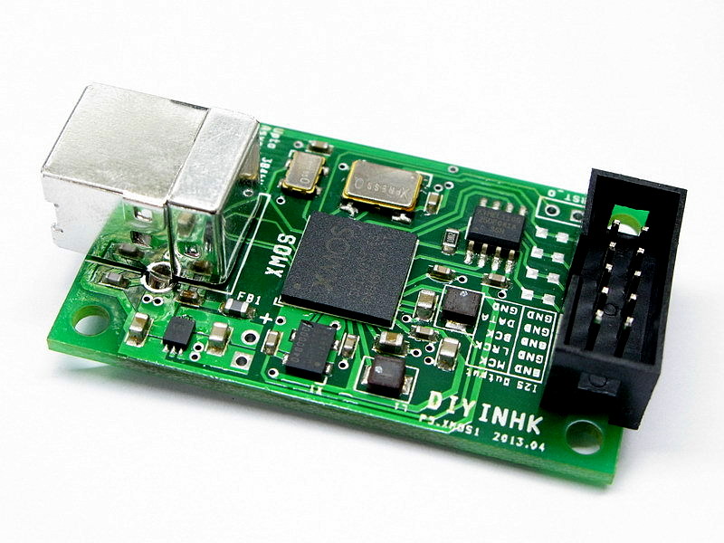
The new board
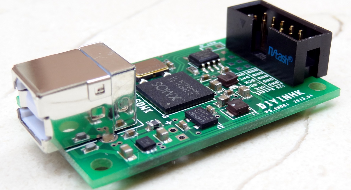
The new chip from XMOS

Cannot tell from the chip markings what part is it. It is “missing” the part number. But it is definitely a “U” part as there is no separate USB controller chip. Here is the datasheet of one version of the part: [link]
The previous generation XMOS devices required a separate USB interface chip (foto from here: [link]):

The audio clocks. According to the datasheet, pin 1 is the enable pin and pin 3 is the output pin. Looks like the enable pin is controlled by the XMOS chip, enabling/disabling the clocks for the corresponding sample rate.


The local ultra low noise LDO (excuse the left over cotton fibers from my cleaning :-)). You can bypass the USB power by removing FB1 and provide external 5V.

The 2 LC filters for filtering the output from the built in DC-DC converters. Here is place to add larger caps and increase the filtering.

Solid ground plane. CN1 is for external powering (instead of using USB power).


If you read the datasheet and compare the topology of this board you will find that the manufacturer has followed the build and layout recommendations from XMOS. In fact it is so simple, that not following the manufacturer’s recommendations is kind of hard 🙂
The new XMOS chip has several advantages over the old device
- Built-in USB receiver
- Requires much less external components and thus it has been optimized to be implemented on a 2-layer board
- Built in voltage regulators. The internally generated regulated power is further filtered by external LC filters – Here is an area to mod: add capacitance to increase the filtering 🙂
- The clocks can be positioned much closer to the device than in the previous design
Apparently 384KHz support was added by diyinhk according to this lively discussion at diyaudio [link]
FEATURES OF THE MODULE (From the manufacturer)
- 6.5uVrms Ultralow noise LDO. -The TI LP5900 [link]
- Solid ground plane (a must for high speed digital circuit)
- No Via in active circuit (via inductance always create jitter problem)
- FOX Xpresso ultra low ppm oscillators and Murata capacitors sourced from Digikey USA. -The two Xpresso 22.579 2MHz and 24.576 MHz clocks. Not the ultimate in low jitter, but pretty low jitter. See the graph below
- Gold plated USB connector
- Compact size 50mm x 30mm. -That is even smaller than the Amanero which is 30×70 mm approx.
- USB powered but can be externally powered by removing FB1 and connect 5V to CN1 (warning: over-voltage or reverse-voltage can damage the XMOS chip immediately. Any modification will void item warranty)
- Can optionally install series resistor to I2S lines (by cutting the traces)
Comparing the Xpresso clocks with Crystek.
DEVICE DRIVERS
I first checked it by plugging it to a Macintosh computer. Native MacOS supports up to 352K and 384K sample rate.

On the PC, it requires device drivers.
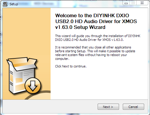
Version 1.63.0 is the latest driver from Thesycon.

No indication of 352K/384K capability for WASAPI shared mode. This may in fact a limitation of Windows mixer as it expects to resample every audio stream to the selected sample rate. However, in WASAPI exclusive mode, this part (the mixer) is totally bypassed and the output sample rate from the player application is passed directly to the hardware.

The driver also supports ASIO
CONNECTING TO DAC
Connected the board to my old Buffalo II DAC (80 MHz clock) and tested all sample rates from 44.1KHz all the way to 384KHz. With the 80MHz version of the Buffalo II DAC, 352.8KHz and 384KHz work fine with oversampling turned off. All sample rates work as advertised. Modern designs are pretty robust, especially this version of the XMOS chip which requires only a few external components.
The socket in the XMOS device matches the socket pin arrangement for the latest version of the $99 ES9018 board and a ribbon cable can be used. For the Buffalo simple cat-5 twisted pairs can be used.


Here is an implementation from a reader with diyinhk $99 DAC board:

The XMOS is hiding…


DIYINHK XMOS USB: The “DXIO”
Straight from the eBay page [link]
I have to congratulate this Mr. diyinhk. He can non only produce designs with such speed, but can somehow price them so amazingly low. This new module is priced at $59.95 -Can’t resist not getting it!
FEATURES
- Latest XMOS chip that uses 48MHz oscillator (rather than the 13Mhz used by the older XMOS chip for the USB interface) – I believe this is the XS1-U chip with built-in USB interface [link]
- 6.5uVrms Ultralow noise LDO. -The TI LP5900 [link]. I believe (the 6-legged chip next to the USB connector).
- Solid ground plane (a must for high speed digital circuit)
- No Via in active circuit (via inductance always create jitter problem)
- FOX ultra low ppm oscillators and Murata capacitors sourced from Digikey USA. -The two Xpresso 22.579 2MHz and 24.576 MHz clocks. They are of different size which reminds me of user complaining when some of the Hiface interfaces were built with the smaller size oscillators. But the industry is moving away from 5×7 mm to 3×5 mm and there is no way back.
- Gold plated USB connector (Molex, FCI, or other -depends on stock)
- Compact size 50mm x 30mm. -That is even smaller than the Amanero which is 30×70 mm approx.
- Module is USB powered but the diyer expert can remove FB1 and use an external 5V PS to CN1 (warning: over-voltage or reverse-voltage can damage the XMOS chip immediately. Any modification will void item warranty)
- Can optionally install series resistor to I2S lines (by cutting the traces)
WINDOWS DRIVERS PROVIDED (NO DRIVER REQUIRED FOR MACS)

Looks like the first USB interface using the latest generation XMOS chip (XCORE USB) with built-in USB.

Amanero PCM and DSD (Update)
This is an update to this post on using foobar to play both PCM and DSD files [link]
Playing PCM and DSD files with foobar:
After installing foobar2000,
From the foobar2000 website, download:
- ASIO support 2.1.2 or newer
UPDATES
Get to the “Super Audio CD Decoder” repository [link]
- Download the latest file from the foo_input_sacd folder
- Download the latest file from the foo_dsd_asio folder
When you extract the zip files you will find:
- foo_input_sacd.dll
- ASIOProxyInstall-x.x.x (application).
- This installs foo_dsd_asio in the default directory C:\Program Files\ASIOProxy
- This installs foo_dsd_asio in the default directory C:\Program Files\ASIOProxy
foo_input_sacd
This plug in shows up as “Super Audio CD Decoder” and allows you to playback the following formats:
- Playback of Super Audio CD ISO images, DSDIFF files and DSF files
- Converts DSD to PCM (if your DAC cannot play native DSD)
To install or update foo_input_sacd, just drag it to the components window in foobar and click “apply”

The control panel looks like this: you can select DSD output or PCM output (when converting DSD to PCM)


More on the different options: [link]
I tested the conversion of DSD to PCM, using both DSD64 and DSD128 files. The results were as expected:
| PCM Conversion |
Output Sample Rate for DSD64 Input |
Output Sample Rate for DSD128 Input |
| 44.1KHz | 44.1KHz | 44.1KHz |
| 88.2KHz | 88.2KHz | 88.2KHz |
| 176.4 | 176.4 | 176.4 |
| 352.8KHz | 352.8KHz | 352.8KHz |
foo_dsd_asio
foo_dsd_asio is kind of a “meta-asio” driver. It is used by the sacd plug-in above as the output device and in turn foo_dsd_asio outputs to an ASIO driver for an actual device. Apparently the sacd plugin does not output directly to an ASIO driver, it must go through the meta-asio driver. (Actually, ASIO itself is a meta-device driver because it talks to the actual device driver)
For one thing, foo_dsd_asio handles the “DSD playback method”: for example, “DoP Marker 0×05/0xFA”. “DoP” means DSD over PCM. Marker 0×05/0xFA means use the marker (for DSD) as specified in the proposed “USB Link for DSD Audio via PCM Frames” open standard [link][link]. This “marker” method is predominantly driven by the MacOS since its built-in USB2 audio driver only supports PCM. On the PC side, there is no native support for USB2 audio so people use ASIO and ASIO can support both PCM and DSD streams. The Amanero board handles “ASIO native”, but other boards may require a marker on the DSD stream.
Thus, foo_dsd_asio has the following functionality:
- Handles DSD playback method
- Converts PCM to DSD (optional)
- Outputs to DSD-capable ASIO driver
To install or update foo_dsd_asio, run the ASIOProxyInstall-0.6.x.exe program.

I tested the PCM to DSD conversion. The latest foo_dsd_asio plug-in handles all sample rates as shown in the following results:

| PCM Sample Rate |
DSD64 Conversion |
DSD128 Conversion |
| 44.1KHz | 2.82 MHz | 5.6MHz |
| 88.2KHz | 2.82 MHz | 5.6MHz |
| 352.8KHz | 2.82 MHz | 5.6MHz |
| 96KHz | 3.07 MHz | 6.14MHz |
| 384KHz | 3.07 MHz | 6.14MHz |
AMANERO FIRMWARE/DRIVER UPDATE
Recall that previously ASIO4ALL was used because the Amanero lacked native ASIO support. Amanero updated the firmware and released ASIO drivers.
For instructions on enabling native ASIO playback, you can follow this excellent post:
Amanero ASIO or you can get the ASIO drivers from the Amenero site [link]. Note that the ASIO drivers compliment the standard drivers and you need both for ASIO support.
After updating the Amanero device with ASIO support you do the following:
Fist set the output to be foo_dsd_asio (in order to support DSD output, and also PCM since this is the output device)

And then in the foo_dsd_asio configuration screen, select the Amanero board.

TIPS FOR UPDATING FIRMWARE
Erase firmware
1- Plug board into USB port
2- Short the pads as shown for at least 1 second (I used a paper clip)

3- Unplug the board
Download and Install Atmel device driver
1- Download and unzip the update tools from the Amanero web site [link]. You will get several files: a device driver for the ATMEL chip, a configuration application for updating the firmware and some other files.

2-Plug the board into a USB port. At this point the device is completely unidentified. You may get a prompt to install a driver or you may not. Following is the manual installation of the ATMEL device driver:
3- Open the Device Manger under the System control panel. The device shows up as “unknown device” as shown below

4- Right click on the unknown device and select Update Driver Software, indicating the location of the driver which is in the folder you downloaded. Your Amanero board is now a “AT91 USB to Serial Converter”

Your are ready to update firmware
1- Ensure that you have erased the firmware as shown above, and ensure that the device is identified as “AT91 USB” as a port as shown below:

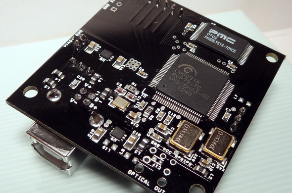
C-Media CM6631A-based USB-I2S Interface
Got a hold of DIYINHK’s C-Media based USB-I2S interface a while back, and it is just now I got around writing something about it.
This is based on the newest USB2 audio chip on the block, The C-Media chip is the CM6631A. This version in turn is the newer, the “A” version of the CM6631 chip which has been implemented in several recent products. The CM6631A differs from the more common (and older) CM6631 in that it supports 176.4KHz sample rate. All other features are the same as the CM6631.
According to the product info page [link]:
USB 2.0 Asynchronous operation (every one does this nowadays)
Up to 192KHz / 32bit
Very capable set of input/output (the implementation reviewed here only implements USB input and I2S output)
- 2 pairs I2S or Left-Justified serial audio output interface
- 2 pairs I2S or Left-Justified serial audio input interface
- Built-in 192K/176.4K/96K/88.2K/48K/44.1KHz and 16/24-bit SPDIF transmitter
- Integrated 192K/176.4K/96K/88.2K/48K/44.1K and 16/24-bit SPDIF receiver
- Supports SPDIF IN-to-OUT loop-back path for signal transforming between TOSLINK and RCA connections
I was able to find an older version of the datasheet for the CM6631 which is pin compatible with the DM6631A [CM6631_Datasheet_v0.8]
It can be seen from the specifications that a more capable system can be developed. For example, a 4-channel I2S output driving two DACs. (allowing performing digital crossover functions in the PC)
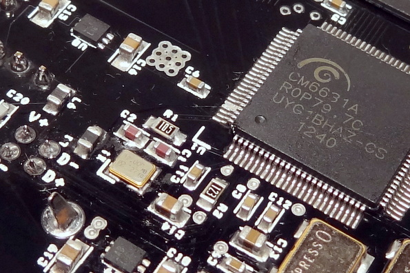
DIYINHK USB Interface: CM6631A (with the “A”)
Top

Bottom. Uses the CM6631A
DEVICE DRIVER
The vendor provides a device driver [link]
Other sources: the latest version of the driver is a unified version for the CM6631 and CM6631A devices, thus available from other manufacturers using either the 6631 or 6631A part (likely they all offer the same versions. some manufacturer may be faster than others in offering newer versions):
I tried the Emotiva provided driver and it works. Here is a screen shot:

FIRMWARE
There are two versions of the firmware as discussed here [link] and here [link]. However, these versions seem to be related to the SPDIF features of the chip. For this board, which only supports I2S, I don’t think these versions of the firmware matters. Note: according the tdtsai [diyaudio], the developer for the driver s/w, the firmware for the CM6631 is not compatible for the CM6631A.
- Firmware 0101 PID 0x0319 can output to SPDIF via CMedia ASIO, but it will never passthrough DTS and AC3. I2S and SPDIF-Out work simultaneously
- Firmware 0108 PID 0x0314, using current drivers, will not output to SPDIF via ASIO, but it can passthrough DTS and AC3 correctly. I2S and SPDIF-Out are reported as different devices (so one output at a time depending on which one you choose)
SALIENT FEATURES
Two ultra low noise regulators: the TI LP5900 [link]

Uses high frequency 45.1584 MHz and 49.152 MHz oscillators to derive the audio frequencies (the manufacturer indicates that these are sourced from Digikey, thus ensuring their quality). This is unique as most devices use half that frequency or lower.

No markings? According to the datasheet, this seems normal. The product number is in the box or reel.

The oscillators output are available to be used as master clock for the DAC. The higher speed oscillator are in the “sweet spot” frequencies for ESS Sabre DACs for synchronous operation.
Since the board does not switch the clock lines, you can only select one of the clock lines to feed the ESS DAC. In this manner, with some of the sample frequencies the DAC will operate in synchronous mode and with other sample frequencies, in the normal asynchronous mode.
For example, if you chose to use the X45 line (45.1584 MHz) as the clock for the ESS DAC, then when playing 44.1K, 88.2K and 176.4K the DAC will operate in synchronous mode and when playing 48K, 96K and 192K, the DAC will operate in asynchronous mode.
You could manually switch the clock lines but this is not only impractical, but it could also upset the DAC requiring a reset.

Easy bypass of USB power. CAUTION: Maximum input voltage for the local regulators is 5.5V

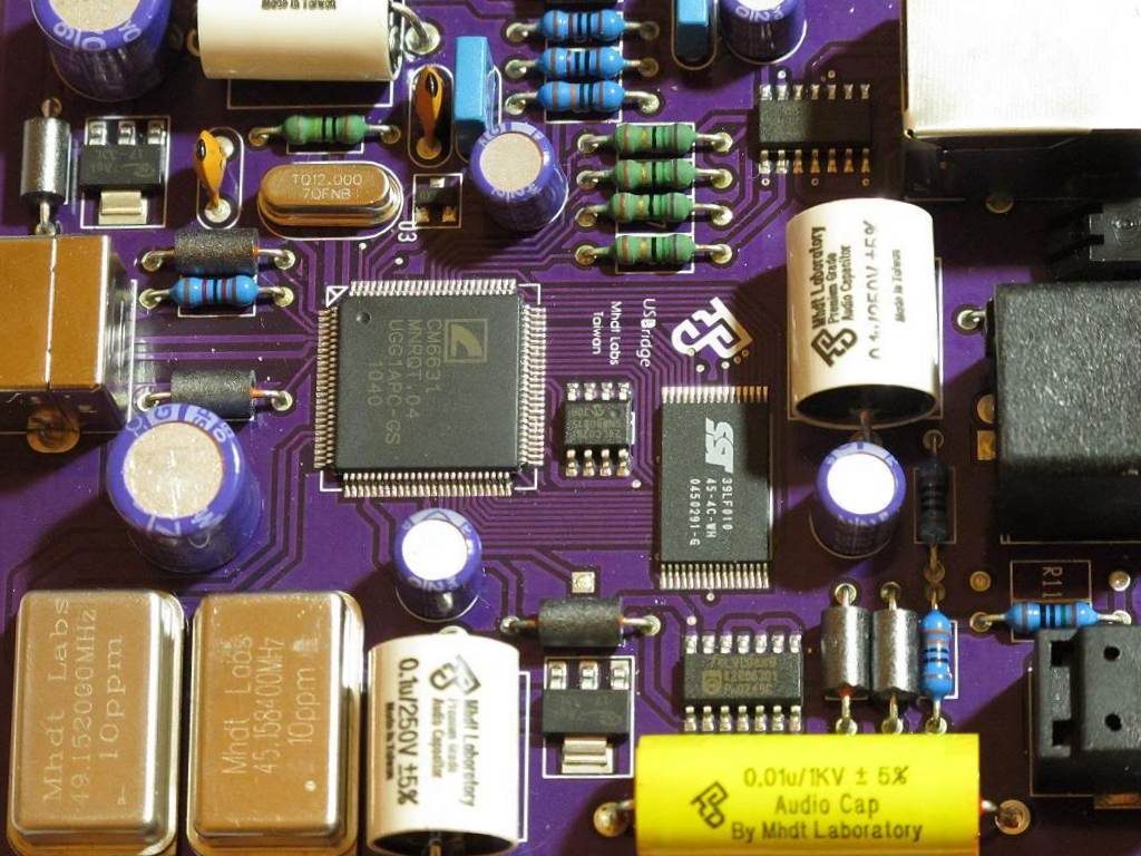
According to the manufacturer, the design employs solid ground plane (a must for high speed digital circuit) and no vias in active circuit (via inductance always create jitter problem). This is apparent from the photo below and in comparison with other designs. The overall layout is very clean and compact.

Datasheet: [link]
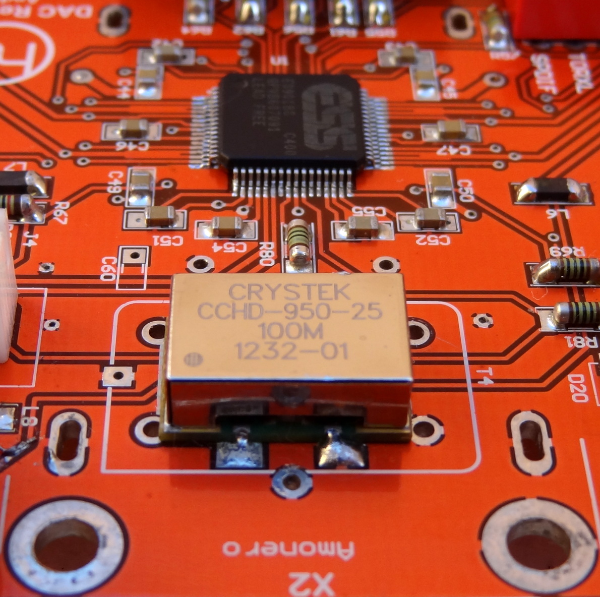
Jitter
The datasheet for the Xpresso clocks is actually very extensive, and the jitter measurement is equally extensive. The phase noise plot is included. I have shown here the comparison with the Crystek CCHD-950-80 MHz which is the oscillator I have in my version of the Buffalo II DAC:
Using the 62,5 MHz curve, we get a phase jitter value of 6 psec RMS (10 Hz – 1 MHz). The Crystek CCHD-950-80MHz has a jitter value of about 2 psec RMS. However, at the lower offset frequencies (the ones of interest to audio performance) the phase noise is not very different from that of the Crystek clock which is a good thing.
INTERFACING WITH BII DAC
There is something “a bit odd” with this interface: According to the specifications:
| DATA | LRCK | BCLK | MCLK |
| 16/24bit | 44.1kHz | 5.6488Mhz | 11.2896Mhz |
| 16/24bit | 48kHz | 6.144Mhz | 12.288Mhz |
| 16bit | 88.2kHz | 5.6488Mhz | 22.5792Mhz |
| 16/24bit | 96kHz | 6.144Mhz | 24.576Mhz |
| 16bit | 176.4kHz | 11.2976Mhz | 22.5792Mhz |
| 16/24bit | 192kHz | 12.288Mhz | 24.576Mhz |
2X BITCLOCK
BLCK is the same for both 44/48K and 88/96K. This means that for 44/48K sample rate, the data is running at 128fs and for the rest of the sample rates, it is running at 64fs.
Even though the Sabre32 DAC specifies BCLK to be 64 fs, it appears that it also supports 128fs. Why? because when I play 44.1KHz material, the DAC reports 88.2KHz sample rate and it sounds perfectly fine. (The sample rate reported by the Sabre32 DAC is based on the frequency of the bitclock, the DAC reports 88.2KHz for 44.1K material)
The sample rate for the higher sample rates are reported correctly by the ES9018 DAC.
Is this a “common” feature supported by other DACs?
The AK 4399 supports both a 64fs and a 128fs bitclock:

The Wolfson 8804 also supports 128fs Bitclock -in DSP mode (p. 44):

So it seems that a 128fs bitclock is not so strange after all. I am not sure if any other dacs support 128fs bitclock, but the Sabre32 DAC definitely does.
OTHER NOTEWORTHY IMPLEMENTATIONS
C-Media has been in the computer audio business since its inception. According to their website, their world’s first accomplishment are all related to audio. Its claim to fame is probably the ASUS XONAR series of PC audio cards and interfaces. The latest ASUS XONAR ESSENCE ONE uses the CM6631 part as shown here (There is a review of the Essence One here: [link]):

The Schiit DACs also use the CM6631 part for their USB option board. As discussed here [link] it does not support 176K material because of hardware limitations in the 6631 part. The “A” part supports 176K sample rate.

The Emotive XDA-2 reportedly also uses a CM6631 chip for the USB interface [link]

The MHDT USB Bridge also uses the CM6631 chip [link]
Have yet to see any commercial implementation using the CM6631A part.
NEW VERSION
diyinhk turns his designs very quickly. This version of the board has been replaced with a new version having isolated I2S [link]

MAC USB 2.0 COMPATIBILITY
There are some reports and fixes to ensure USB2 compatibility with Macintosh computers: [link] with certain CM6631-based implementations.
This board does not suffer from the reported problem: there are no 3-pin devices near pin 98 of the chip.
Plugin this device into a Macintosh computer shows that it is indeed a high speed USB 2.0 device as shown in this snapshot of the CMEDIA device under the USB description screen
JITTER IMMUNITY TEST
Here is a reported test of the CM6631A (implemented in a different device) showing jitter measurements with and without processor load and comparing the asynchronous nature of the USB communication vs a device using USB adaptive communication. [link]
In his conclusion, this device (as well as other USB-asyncrhonous devices) show great immunity against processor loading:
Bottom Line: Don’t worry about jitter! It’s more than likely inaudible in a modern computer system and with decent (not necessarily expensive) audio gear. I see no evidence that high CPU/GPU load makes any difference to jitter. Isolating your DAC from electrical noise polluting the analogue output seems much more important.

Latest Comments