INTRO
This blog has been sort of a notebook for me to write down my own learning with Arduino and the TPA boards. Therefore the information presented assumes that the reader’ is learning at a pace equal to mine.
Beginners are overwhelmed with the amount of information here so this post is to help those by outlining the basics of building a controller board for the superb kits produced by Russ and Brian of Twisted Pear Audio. TPA is also developing a controller for their products so this is an alternative to their solution utilizing low cost, and widely available parts. (As of July 2011 April 2013, the TPA controller board in not yet available, so this is the only “ready-to-run” option)
Basically, all modern audio chips have a software interface and they communicate with a micro-controller through a communication protocol called “I2C”. I have chosen the Arduino platform because I am not a programmer and Arduino is geared towards that audience. In addition, the Arduino community provides a lot of help for beginners and non-programmers.
HIFIDUINO is about building a controller that can talk to those audio chips. So far I’ve interfaced to the OPUS DAC with the WM8741 and the Buffalo II boards. But the same platform can be used to interface to other chips such the WM8804 spdif interface and even the brand new TI PCM51x2 DACs with lots and lots of features that are available only through s/w programming.
The controller consists of:
Arduino board
NOTE: if you use Arduino UNO R2, there is a potential bug: https://hifiduino.wordpress.com/code/#comment-718
Any official board or clone will work. The current (v.09) code size is about 14K bytes, so even the bottom of the line Arduino will work. All of he following models work: UNO, Dueminalove, Seeeduino v.2.2, NANO and others. I have used the UNO and the Dueminalove. I have even used the Freeduino. If you want to be dead sure that it will work, then purchase the latest official Arduino UNO (R3 or above)
The Freeduino with a companion stationary shield
Rotary encoder
The rotary encoder is used to change volume and settings. In theory, you can use any “quadrature” or “gray code” encoder. However, I find that the preferred characteristics of the encoder are:
- About 30 cycles per turn. This gives a good “feel” when changing the volume, changing 30 db per revolution -not too fast or too slow
- Built-switch. The switch is used to change from volume control to DAC settings control. This is not mandatory, you can implement with a separate switch
- A rotary encoder with “clicks” is preferred because you can feel the clicks when you select the different settings. I tried a rotary encoder without “clicks” and it does not work well because selection of the different settings take advantage of pushing the encoder to activate the switch. Often one you push the switch you can also inadvertently move the encoder. Rotary encoders without detentes (“clicks”) are not recommended.
I use a Panasonic model that has been discontinued, but available from Electronic Goldmine. Other candidates are: Bourns PEC11, BI EN12. The current version of the code (v.09) does not require that you build a debouncing circuit as the debouncing is done in the software (I had used the rotary encoder without hardware debouncing or a long while, but I finally added the debouncing capacitors).
LCD display
The code assumes a 20×4 LCD. Any LCD that is compatible with the HD44780 protocol will work with the code: Do a search for “20×4 LCD HD44780” on eBay. The one I purchased is from Sure Electronics. You can also purchase directly from their website: [link]. Nowadays it is available pretty much everywhere. Here is another good source: iTeadStudio
As it turned out, a larger portion of the code is the user interface and it assumes a 20×4 LCD. Thus, if you use a different form-factor LCD (for example a 16×2 LCD, you will have to overhaul a lot of code.
NOTE: if you use Arduino UNO R2, there is a potential bug: https://hifiduino.wordpress.com/code/#comment-718
IR receiver and a remote control
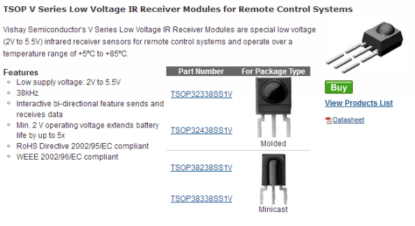
The code supports the Apple Aluminum Remote. Any IR receiver should work. However, I would recommend the Vishay TSOP32438 because it is designed for the 38KHz frequency used by the Apple Remote. The 32438 model also provides noise immunity. Additional information: [link]
Here is a good article on “how to choose IR receiver”: [link]
In fact, any one of these would work:
A level converter from 5V to 3.3V for the I2C lines
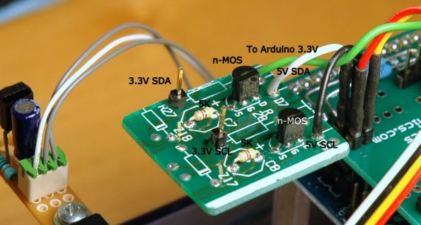
This part maybe optional. As the I2C inputs of the Buffalo are “supposed to be” 5v tolerant, but the data sheet does not say specifically and I have not determined that to be the case with 100% certainty. (You can easily build it if you do not wish to buy the module)
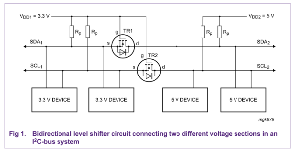
You can build your own level shifting by following this diagram from this document [link]
I Made my own here: [link]
GET GOING
The best use of this project is for you to experiment with your own choice of components and ideas. You can reuse whatever part of the code you wish (as I have reused code from other contributors. -This is the spirit of open hardware and software of the Arduino community). If you do this you will find that the audio hobby is not just about changing cables, capacitors and power supplies 🙂
However, if you wish to just replicate what I have done, this is what you do:
- Get familiar with the Arduino development environment. At the minimum you must know how to compile code and upload to an Arduino. The Arduino tutorials listed in the side bar are a good start.
- Procure the parts above and hook them up according to the different hookup diagrams in this blog. The current code does not require that you build a debouncing circuit for the rotary encoder so you can skip the debouncing circuit
- IR receiver hookup
- Rotary encoder hookup (follow the “no H/W debounce” diagram)
- LCD hookup
- Level converter hookup
- Download the latest version of the code from the code tab. Compile and Upload to the Arduino
- Done!
This is what my controller looks like:
User Interface summary
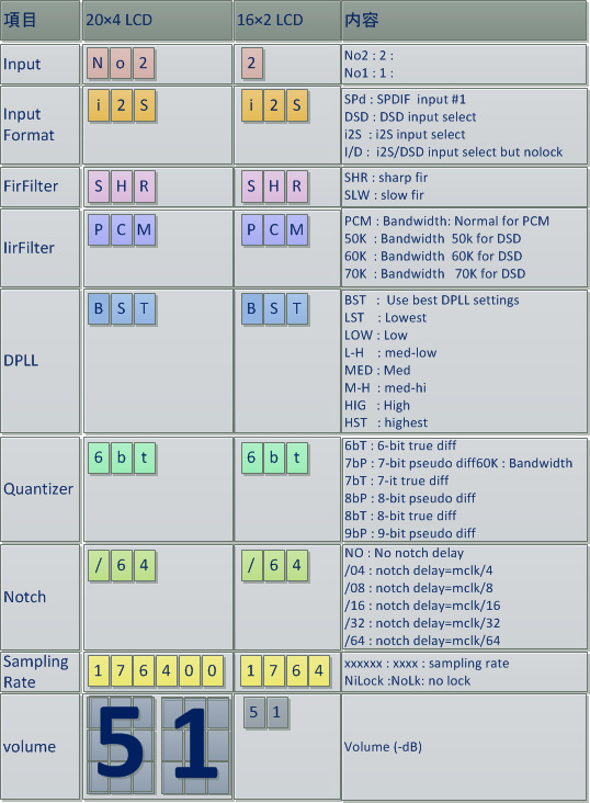
Here is a very nice summary of an older (v. 09) user interface from マルチチャネルDAC製作記 blog and in particular this post [link]
I have updated the user interface a bit: https://hifiduino.wordpress.com/2012/01/09/code-compatible-with-arduino-1-0/
Newer versions are a refinement. But the overall user interface is pretty much the same
NOTE: if you use Arduino UNO R2, there is a potential bug: https://hifiduino.wordpress.com/code/#comment-718
EASY ORDER (DIGIKEY)
Arduino UNO R3: 1050-1024-ND [link]
ANOTHER IMPLEMENTATION
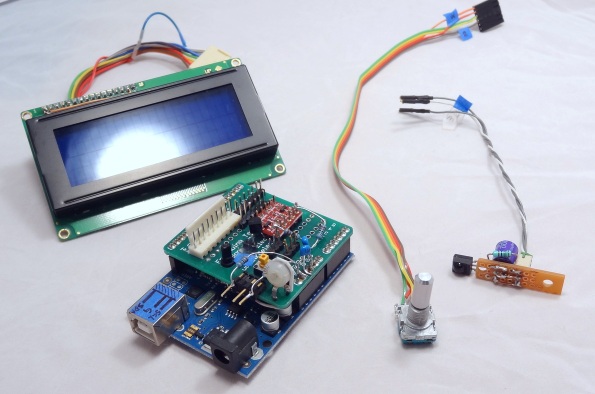
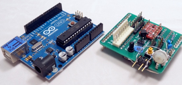
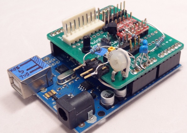
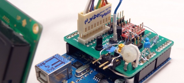
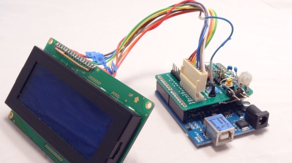
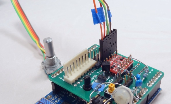
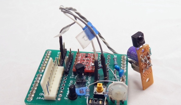
Here is another implementation of the controller with a hand made Arduino “shield” to facilitate connections: LCD, Arduino, shield, rotary encoder and IR receiver.
The shield has the following components:
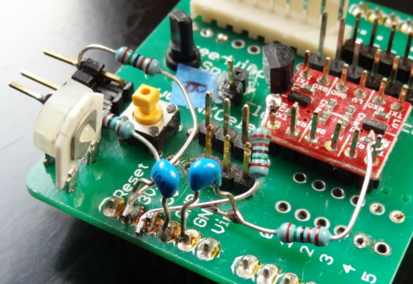
- 5V to 3.3 Level translator with external pull up resistors (1.5K ohm) and local 0.1 uF power supply (5 and 3.3V) bypass. This will ensure clean I2C signals. External pull ups may or may not be required. Depends on your environment.
- Potentiometer for LCD contrast adjustment
- Potentiometer that adjust the current to the base of a transistor controlling the brightness of the LCD
- Arduino reset button (since the reset button of the Arduino is covered by the shield)
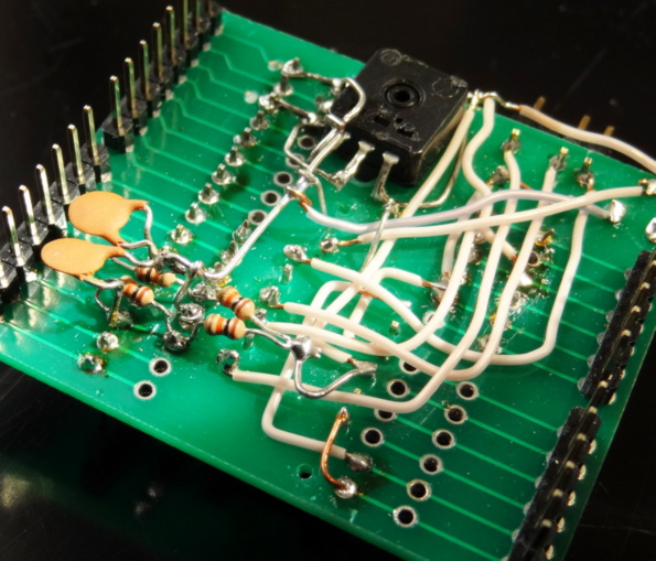
- Underneath, I had implemented a debouncing circuit for the rotary encoder. The code does not need the hardware debouncing circuit since it uses s/w debouncing, but it does not hurt.
The external 1.5 Kohm I2C pull up resistors were added afterwards to solve a noisy I2C connection. In most cases, the internal pull-up resistors or the pull-up resistors built-in in the level translator board should be good enough. I had also added power supply bypass capacitors to further clean up the I2C lines.
The h/w debounce circuit was built in accordance to a BOURNS “Signal Conditioning Technical Note” paper [link]. This is not required by the current version of the code because s/w debouncing is used. However, it is always a good idea to reduce spurious interrupts.
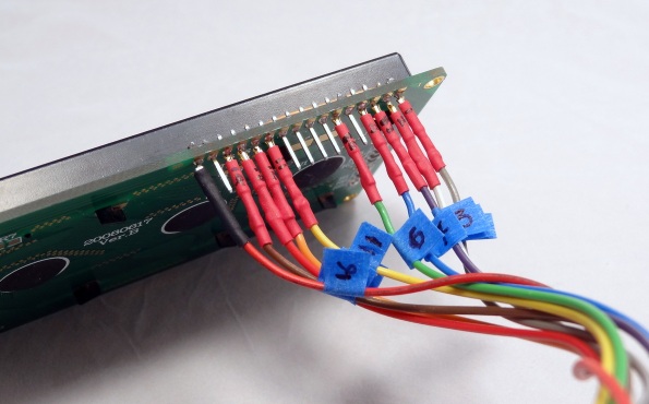
Connecting the LCD
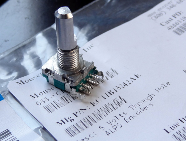
Connecting the rotary encoder (with switch)
I find this rotary encoder very good. With solid clicks and good feel. You really need a rotary encoder with “clicks” because it is also used to make adjustment. I had also used an encoder without clicks and as you push the encoder to actuate the switch and make selections, you would also slightly rotate the encoder making inadvertent adjustments.
More info on rotary encoders:
Connecting the IR receiver





Hi! Great blog just burned the last 2 hours reading your posts.
Even though I have some experience with Arduinos and a little with DACs (working in a laboratory) I was wondering if you could recommend a easy guide of a full built to get started (including some links where to order stuff).
Thx in advance
Michael
I enjoyed writing the blog 🙂
The information here tells you what to buy and where…
The software described here works with the buffalo DAC. You can check http://www.twistedpearaudio.com
Hi, this is fantastic! Thanks for posting all this. I want to build my own 5v – 3.3v converter and see in the above photo that you have done the same. Can you point me in the right direction to a circuit diagram or list of components etc?
Cheers!
Added info in the post…
Hi GLT, Your work here is much appreciated as in diyaudio. Thanks a lot!
I’ve added “the system” to my diyinhk es9018 v.5 DAC. I use sainsmart uno R3 with large 20×4 LCD. Nothing has any frills! I made hifiduino successfully work in a way, only with one problem: the DAC requires reset once hifiduino starts, and each time when something is attempted to be changed (such as volume and other settings) through the remote or rotary encoder. Some basic nut or bolt is loose I suppose!!
If you have any insight what might be the culprit or which direction should I look will be very helpful.
Thanks in advance.
Tell me more. What happens right after you power both the DAC and Arduino. Usually you can start them at the same time. If you can externally mute the outputs, you can startup the DAC first and then Arduino. Also, I would recommend having all the wiring as twisted pairs (I2S and I2C) and make sure no wires crosses over the DAC chip
Thanks for your answer. At the moment I have seperate power supplies for the DAC and Hifiduino unit with seperate switches, but starting them at the same time will not be a problem and eventually it will get the power from DAC psu. The problem with any interaction of Hifiduino with the DAC causing stalling I think may be due to current I2C wiring, which I haven’t tried to perfect it yet. Do you think using pull up resistors on SDA SCL lines will be any help? My DAC is very clean, with all seperate Salas shunt regulators after two stage inline regulation, etc. although everything is still on test setup, with minimized and careful wirings. I’ll try powering up both units at the same time and work on I2C line and I’ll post more info later
Thanks again.
F. Arhun
I haven’t encountered any scenario where I have to reset the DAC. When there are problems, I’ve had to reset the ARduino. In certain environments, adding pull up resistors to the I2C would be beneficial. Check out this post: https://hifiduino.wordpress.com/2013/03/25/new-version-of-code-2/
I also made me a small system with a DIYHK PCB. 🙂
No leveltranslater used, because the DAC’s I2C pins are 5V convertible.
I use an I2S signal, and I can see the samplerate is changing on the display (Means the system is communicating with the DAC and I’ts running), but I can’t measure any output of the DAC. I use 100 ohms resistors on the output, but I assume I should be able to measure something else than a DC voltage?
Do I need to remap the DAC different compared to the BII DAC?
Great page btw.
If you are using the I2S inputs of the diyinhk board, there is nothing to change. How are you measuring? Unless you have an oscilloscope, it is not easy to measure music with a voltmeter…
I just found your great block. I wonder if your code can be used with Buffalo 32s
I believe it should work as is. Just try it.
Thanks. Order Arduino board and other parts already. Should be fun.
Just finish asambly but can not control the dac. On display board, it show no lock in up right corner. But the system play music as usual. The Buffalo 32s is locked to Mac mini using itune and audirvana plus fine. Could you please guide me to the right direction.
Did you remove the microprocessor in the B32S? only one microprocessor can control the board.
I did. First time that I connected I have not remove the microprosessor in Buffalo32S and Arduino just freeze, the screen show all white. Then I turn everything off and remove microprocessor in Buffalo32S and connect again, Arduino turn on normal with welcome screen and display response when I turn encoder. I try both open and shut Address pin on buffalo32S with no effect. I have not connect the IR receiver thought.
So the chip is not responding at all. The default address is “open pin”. Ensure the I2C wires are correct. Also need to connect GND between Arduino and DAC. Can you post some photos somewhere?
I2c wires are checked. Ground is connect. Let try picture. https://www.dropbox.com/s/mj2q0djhi08cul1/Photo%2019-6-2556%2C%2021%2048%2019.jpg
I first connect with level converter that I order. But last night I build it my own because I thought the level converter was not function but that was not the case
Picture https://www.dropbox.com/s/zkosq9gmdqhqjd3/Photo%2019-6-2556%2C%2021%2049%2050.jpg
Can’t see anything that is obviously wrong. Things you can try:
– Use the older Arduino 1.0 (I have not upgraded the Arduino IDE to the latest one)
– Try adding pull ups to the I2C. (I have used 1.5K pull ups in noisy environments)
– Flip the I2C wires
– See if the I2C lines are indeed connected to the chip (I suppose you have the datasheet)
– If the Arduino does not freeze, and changing the volume does nothing, then either the Arduino is not communicating or the DAC is not responding – I have never experienced this. Typically if you have noise in the I2C, the Arduino would hang…
– In theory, there is no difference between any of the Sabre32 DACs. I’ve heard people using it with BII, BIII, Acko, diyinhk and QuangHao DACs
– Good Luck!
It works now!!!. Flip the i2c wire works. May be Buffalo32s have a mistake in printing.
Thank you so much in helping me figure this out. Really appreciate your help.
Enjoy!
How does one contact with you about a project I see here.
This is quite exciting to me –
HiRes SD Card Player: SDTrans192 v. 3.0
Thank You,
Mark
That project belongs to Mr Bunpei at diyaudio.com
If I turn the volume al the way up to 00, without a DAC connected, this value is stored in eprom right? because If I power up the adurino it’s back to 50
This is how the code works. The volume is not remembered. Every time it starts with a default value. The Default value can be changed.
This is to prevent starting up with a high volume if you were listening to high volume before…
Was thinking of using an Adafruit Pro Trinket 3V 12MHz board but they don’t have pins 2 and 7 available. Is it possible to reassign your pin 2 and 7 functions to, say, pins 6 and 13?
Have had a look at the code and believe that, although I’m new to this, I can take a stab at altering the pins. Only doubt is, I read a comment saying pins 2 and 3 are interrupts; so if 2 is not available on the Pro Trinket and I have only one interrupt pin, am I sunk?
Haven’t got all the bits yet but will take a shot at it unless you say it can’t be done with the Pro Trinket. I need a small footprint controller to fit it all in.
I am only using one interrupt. You will have to use that interrupt pin for the rotary encoder.
Okay, thanks. Once I get everything I’ll report progress. And thanks for the project.
Got it to work with the Adafruit Pro Trinket 3V. Minor alterations to the code for the LCD pin inputs and interrupt. Also, because the Pro Trinket is 3V there’s no need for level converters with the diyinhk K2M. Used an Adafruit quarter-size perma-proto board so it’s a very small footprint.
Used with an Alix SBC using Voyage MPD and a Class D module to make an ‘all-in-one’ music server/remote controlled volume control/amplifier unit that fits on an 11×16 base – including linear power supplies.
As it’s the first time I’ve ever used any kind of microcontroller or code I’m grateful for the extensive blog and explanation on the code – much appreciated. I’m old enough to still be amazed by what people will share on these blogs. Tip of the hat to you, sir.
Only issue so far is that when I first plug it in the volume is really loud until I move the rotary encoder or touch the Apple remote. Will go through the code and blog again as I recall seeing something about muting the DAC on startup. May also just require stopping the music server before powering down so it does not boot with music playing – although that’s not always under our control!
Thanks for a great project.
The issue is that when the micro-processor is programming the registers (eg setting the volume), the DAC is not ready. If you turn the DAC first, then it will be at full volume. But when the microprocessor starts it is able to program the registers and lower the volume. In the past turning on both the DAC and the microprocessor at the same time (at least with the regular ES9018 DAC), the DAC seems to start just a tiny bit faster than the microprocessor, so that you get loud volume for a fraction of a sec and then the microprocessor sets the volume to the default value.
The solution for this is not to have any active source during startup.
Hi Derek,
would you mind to share your code for the pro Trinket?
Branko
Minor changes. Because the ProTrinket 3.3V does not have pins 2 and 7 you simply change the line for the LCD pins from ‘LiquidCrystal lcd(12,11, 10, 9, 8, 7)’ to ‘LiquidCrystal lcd(12, 11, 10, 9, 8, 13)’ and, of course, wire the pin 7 LCD wire to pin 13 on the ProTrinket.
To take care of the lack of pin 2 on the ProTrinket you change the original line ‘#define ROTPINB 2’ to ‘#define ROTPINB 3’ and wire the rotary encoder pin to the ProTrinket’s D3 instead of the non-existent D2.
Finally, because the original sketch used D3 as the IR receiver’s input pin you change ‘# define REMOTEPIN 3’ to ‘# define REMOTEPIN 6’ and wire the IR receiver’s output pin to D6 on the ProTrinket. Pretty simple and straightforward.
Just remember it needs to be the 3.3V version of the ProTrinket to avoid the level changing.
Apple Remote only? Some may want to keep it simple. Use an Arduino Nano or the Pro Mini, a MCP42010 digital pot to the Buffalo III (SE) volume input and the IR receiver shown in the Intro section. First, I built the Hifiduino with a LCD then a graphic display. For my second build I liked the simplicity of using the Buffalo’s controller (which worked with DSD using Foobar and up to 384KHz sample rates using the Amanero USB interface) and its built-in volume input, connected to the MCP42010. Works great.
You can use the Apple Remote code in Hifiduino to receive the IR codes. Decode this up/down, left/right (fast volume change), volume reduction (center) and mute (pause). Increment/decrement a Volume variable (byte) and send it out using Serial Peripheral Interface to the pot.
// REF: CE-DESIGN.NET and http://little-scale.blogspot.nl/2007/07/spi-by-hand.html
// SPI functions were copied from CE-DESIGN.NET
// getIRkey function and decoding framework is from HIDUINO but ramping is modified
// and Volume is direct instead of using attenuation as used with the Sabre DAC.
Hi
Trying to implement your code, but cant get a lock on my source. Using the sidecar to switch between the 1:4 mux and the exa i2s. Should I connect the arduino directly to the sidecar to make this work (i this supporter by the code?)? or should I remove the sidecar and mux and try to hardwire the inputs?
There is no code to support the side car. Try hardwire first and work from there.
Thougth so. Just had to ask before i cut the sidecar off. Second-hand Buffalo and was stuck right on the board with silver solder. Works now though.
Hi, very interesting post! Do you have any suggestions for the filters included in the Opus DAC WM8741? And did you try a direct DSD aplication with the Opus and the arduino in control? Thanks!
Didn’t try the DSD capability of the WM8741. The DAC does not share the same inputs as I2S, so you need to switch to different input pins if the source is DSD. Not as convenient as for example the ESS DACs. More info here: https://hifiduino.wordpress.com/2012/11/22/pcm-i2s-and-dsd-on-the-same-wires/
Regarding the filters, I couldn’t tell much differences between the different filters. Some of it due to reduced high frequency hearing due to age… More info here: http://hifiduino.blogspot.com/2009/11/testing-wm8741-filter-setting.html
Hi,
I have doubts about my configuration. Maybe someone can help me here:
I have a dual mono configuration Opus DAC and I want to use I2C with an Arduino Uno R2 to control the two dacs with the same input from arduino. I don’t know if I can do a parallel from the 3.3V line of the level-shifter to the two dacs or if I’ll have to do it independently for each DAC because of probable interference between two DACs. What are your thoughts about this?
Thanks
Yes you can, the I2C protocol is designed to work with multiple devices, this is why you send a device address first.
I am having problems with LCD. I started with a display behaving good, then it got corrupt characters after some minutes, now it shows only squares. Every now and then shows readable characters in upper left corner.
Noise, bad connection or some timing issue in code? Confuses me as it has gotten worse over time. I cannot find any bad connections, and rerouting cables seem to eliminate noise theory.
Thankful for any ideas.
Fred
iphone repair worcester
Make your resume fast with Workiza
martini shaker set
49.95 any sewer or drain
ibuprofen 800mg
what is alkaline water
Hi
Are they ready to use kits for ES9018k2m ? (diyinhk)
Don’t the controller inject some noise into the DAC ship though I2C ? there is no isolation…
thank you
B.
Hi, I have a TPA’s Buffalo32S DAC which also uses the ESS9018. The board is also provided with I2C. Will this project work with it?
Thank you
Prakit
BTW, great blogs, great writing!