Soekris dam 1021 R-2R DAC ILLUSTRATED GUIDE
(03/24/15) Updated the filter table.
I am consolidating all the user-level information in this post that is spread through several other posts. Where needed, I will clarify and include the latest available information.
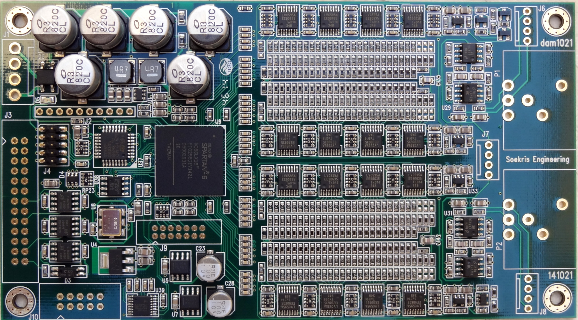
GENERAL LAYOUT
Ref: [1527]
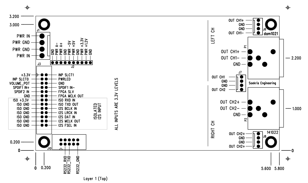
Note: in the diagram above the labels for “RIGHT CH” and “LEFT CH” are swapped. This was noted in the forums [1147] and I also checked it with a R/L test track.
The correct channel assignment (when viewed from the output side) is:
- Right Channel is on the right hand side
- Left Channel on the left hand side

NOTE: it could be possible to swap channels in software, but not possible with the current version of the firmware. Channel assignment is required for mono operation.
Update: firmware 0.99 [link] allows you to configure the DAC as MONO Left or MONO Right, but you still cannot swap the channels.
AUDIO INPUT CONNECTIONS
The dam 1021 supports the following input connections:
- Two SPDIF inputs.
- One Isolated I2S
SPDIF Inputs
You may use one for Toslink and one for transformer isolated Coax as follows [1108]
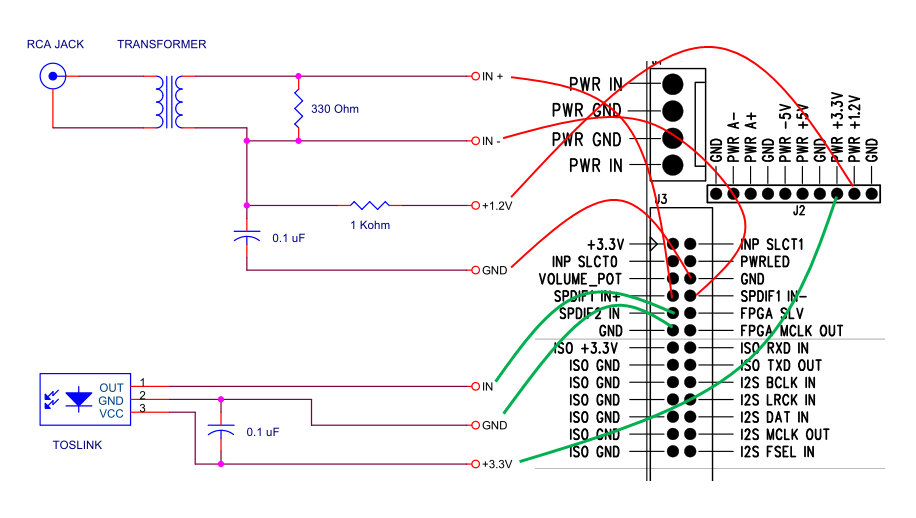
Notes:
1.2v and 3.3v power can be taken off the DAC board as indicated in the diagram.
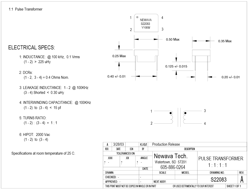
The isolation pulse transformer for the COAX input is a 1:1 type. The Newava Technology Inc S22083 is a favorite [link]. You may find more recommendations in the diyaudio implementation thread [link]
A toslink receiver can be wired as shown in the diagram. The Toshiba TORX147 [link] is a favorite. Seems Toslink receivers are hard to find in the component stores. eBay seems a good source [link]
A nice Toslink module is the one from Twisted Pear Audio [link]. (It is the one I own). This one has an on-board 3.3V regulator (IC1 in the diagram below) and is to be powered by 5-12V DC. This one has the Toshiba TORX142 module (25Mb) with supports up 192KHz sample rate (data sheet: torx142l), but Toshiba stopped making them. The current one that is on sale at the TwistedPear Audio store is specified to support up to 96KHz and uses the popular and current Toshiba TORX147.
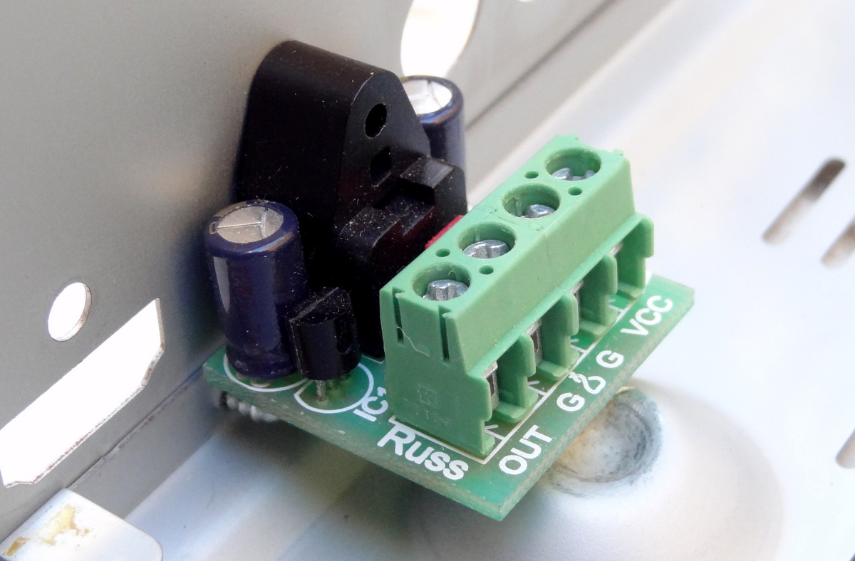
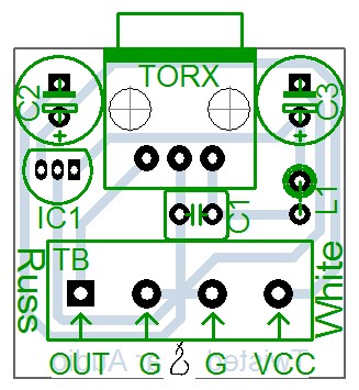
DIYINHK Also has a very inexpensive ($4.00) Toslink receiver: [link]

The difference with the one from TPA is the lack of a local voltage regulator, so you need to provide 3.3V power (which is readily available from the DAC board)
I2S Input (Isolated)
The dam 1021 DAC implements a FIFO reclocker and therefore it does not need master clock input. It works similarly to many modern DACs where an internal PLL or equivalent circuitry locks to the bitclock and generates its own master clock.
The I2S input lines are also noise-isolated with Silicon Labs digital isolators [link]. This means that power needs to be provided to the isolator chips.
Thus the following connections are needed
- Connect I2S source BCLK to DAC I2S BCLK IN Pin
- Connect I2S source LRCK to DAC I2S LRCK IN Pin
- Connect I2S Data to DAC I2S DAT IN Pin
- Provide source 3.3V to ISO +3.3V Pin
- AND connect I2S GND to ISO GND
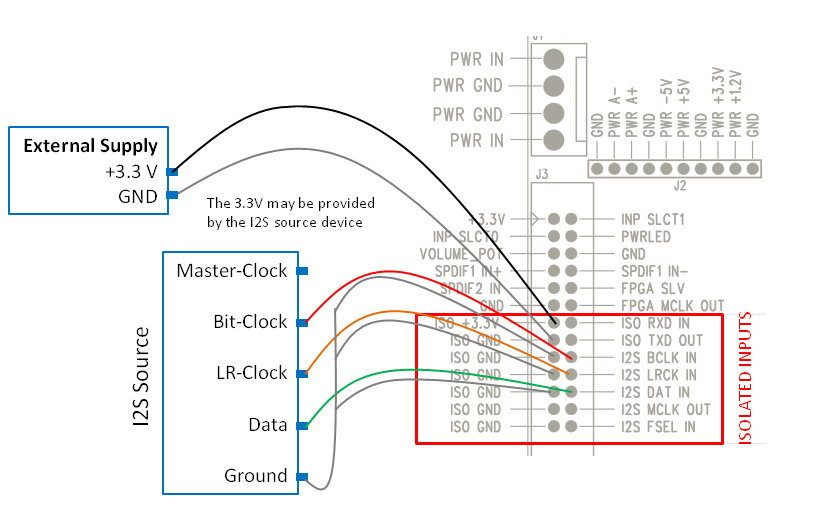
You may also also tap into a 3.3v line in the I2S source if an external supply is not available.
Here is an example using diyinhk USB to I2S adaptor:
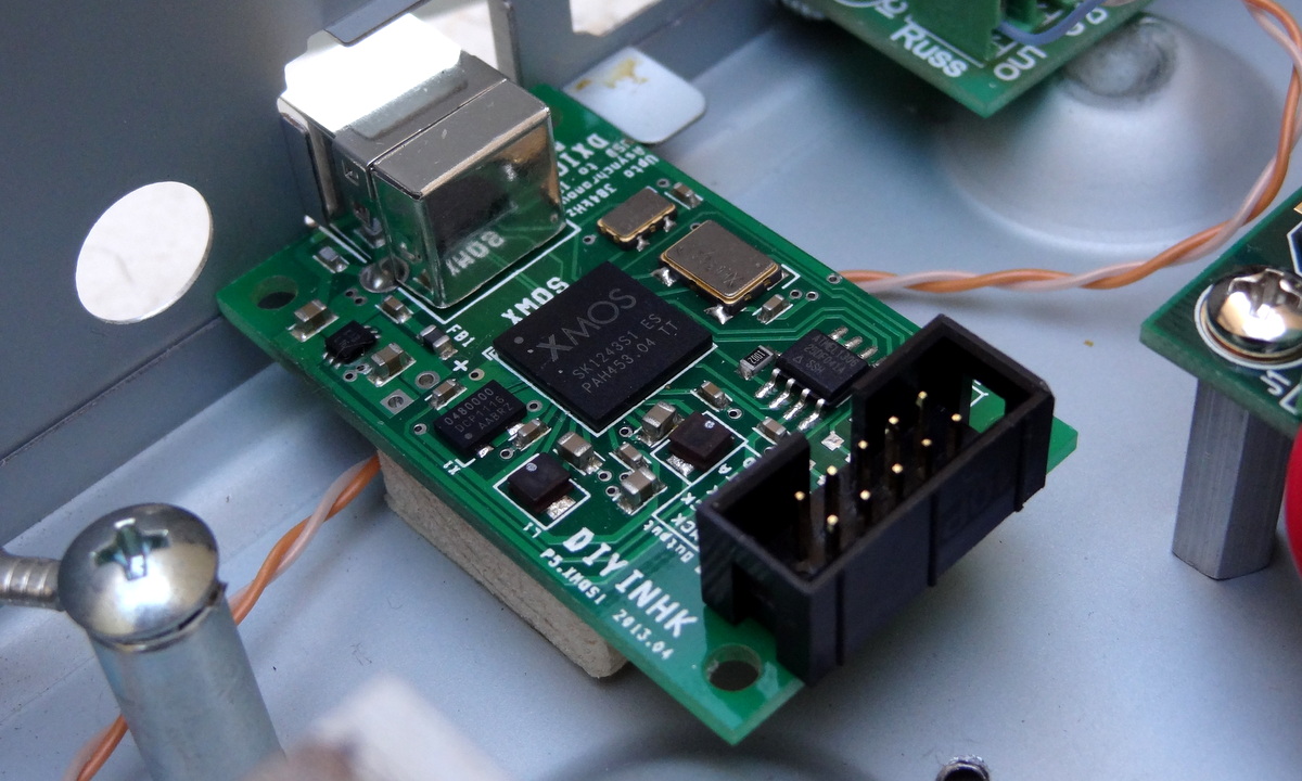

The I2S wires (the multicolored ones)

5V for the ISOLATED INPUTS
According to the data sheet of the the Silicon Labs digital isolators on the board [link], the supply voltage can be 3.3V or 5V. With 5V you can use I2S inputs that are 5V. I have been using 5V supply and works well with 3.3V input signals.
Note that the isolator works by having separate power supplies on each side: the clean side (which is the DAC) and the “dirty” side (which is the I2S source). In order to provide complete digital isolation – meaning “isolated power and ground”, the two supplies must be completely separate. More here [link].
The power supply of the clean side is provided by the DAC board and cannot be externally accessed. The power supply for the “dirty” side is (and must be) provided externally.

Input Selection
The DAC supports automatic or manual input selection as follows:
| Input | INPSLCT0 Pin (J3) |
INPSLCT1 Pin (J3) |
Description |
| Auto Selection | Open | Open | DAC will search the 3 inputs for a valid signal and lock when a valid signal is found |
| I2S | GND | GND | Note that even when not used the USB-I2S interface might output a clock that the dam1021 lock on to…. |
| SPDIF 1 | Open | GND | This input is a sensitive LVDS Receiver -used for Coax [1076] |
| SPDIF 2 | GND | Open | This input is a standard 3.3V digital level -used for Toslink |
I recommend you try Auto Selection first (there is nothing to do). It works very well. Then if you have several sources and more than one active at any time, then implement some circuit (or use an Arduino) to select the desired input.
Signal LOCK indicator
- Steady on: signal lock
- Blinking: no signal or no lock

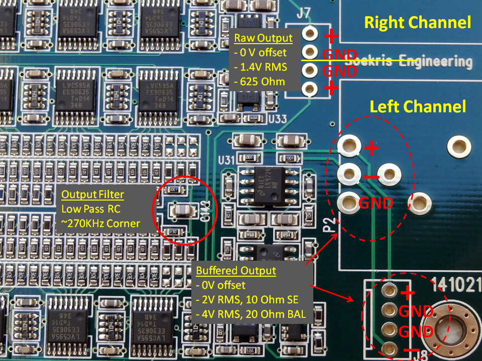
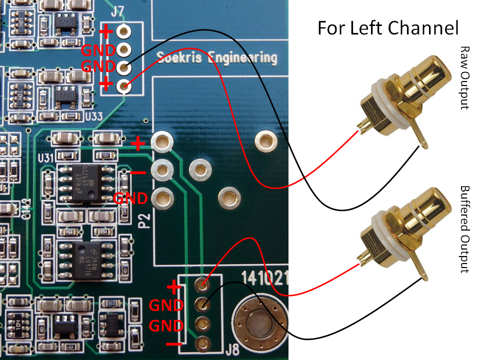
AUDIO OUTPUT CONNECTIONS
The dam1021 DAC provides the following outputs
- Stereo single-ended RAW outputs
- Stereo balanced buffered outputs which can also be used single-ended
- Both outputs are active and can be used concurrently
RAW outputs
The raw outputs come straight from the resistor ladder passing just through a low pass RC circuit. Raw outputs provide the cleanest, unprocessed output possible most desired by audio purists. It can be connected directly to an amplifier which typically have high input impedance (>10K ohm).
Note: Balanced offset has been measured to be 2V [link] -need to confirm…
Buffered Outputs
The raw output signal is also routed to a buffered single-ended to balanced signal converter as shown in the following diagram:

Buffered Outputs Balanced Connection

Buffered (and RAW) Outputs Single-ended Connection

The buffered outputs are designed to drive high impedance headphones directly. Here is an example connection to headphone outputs:


I am using a Sennheiser HD-580, with a 300 ohm nominal impedance [link]. Sounds fantastic.
CAUTION: direct connection to an amplifier can result in passing the power on/off pops of the DAC potentially causing damage to the speakers. Follow proper power on/off management: turn the DAC on before turning on the amps and turn the DAC off first before turning off the the amps turn the amps off before turning the DAC off. This power sequence will ensure that the pops will not go through the amplifier circuit to the speakers.
If you are using direct connection (of the buffered output) to a headphone, the pops would be annoying but, at least in my case, they would not damage your headphones.
DIGITAL VOLUME CONTROL
Reference: [link]

The built-in digital volume is enabled with a potentiometer connected as such:
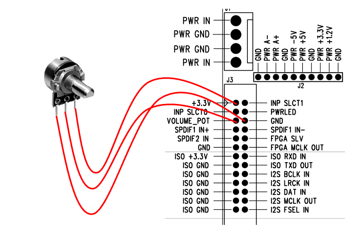
The nominal value for the pot is 10K ohm but any pot would probably work because it is used to set a voltage between 0 V and 3.3V to pin “VOLUME_POT”.
The typical configuration of a potentiometer is the one shown above where the middle pin is the wiper and the end pins are the end connections to the resistance. If you find that your potentiometer does not work as intended you can follow this simple method:
- Find the two “end” pins by measuring the resistance as you move the knob. When then resistance does not change when turning the knob, those are the “end” pins that connect to 3.3V and 0V. The third pin goes to the VOLUME_POT pin
- If you experience that volume decreases when turning the knob clockwise, reverse the connections
If nothing is connected, the volume level defaults to 0 db.
The advantage of using a potentiometer, as compared to using a rotary encoder (which at the moment is not supported anyway), the DAC always starts with the last volume setting.
POWER CONNECTION
The DAC implements several local regulators and therefore it is designed to operate out of a single center-tapped transformer. It can also work with DC input.
The requirements and specifications for the power supply or transformer are as follows [901], [848], [1130]
- DC: +/- 7.5V DC to +/-15V DC; preferable 9-12V DC
- AC: dual secondaries 2x 7-8V AC or center-tapped 0-16V AC
- Power consumption: 2.4V. Thus a 5W transformer is preferred
Transformer Hookup
A favorite transformer is the Hammond 229 series [link] it is a “dual-split bobbin” design with low EMF radiation. It is a step up from the standard low cost transformers.

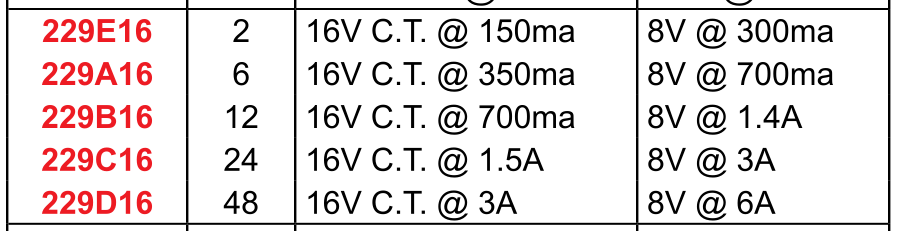
A 229B16 (rated at 12VA)would be an excellent fit with ample power for DAC. It is available at Digikey for about $16 [link]
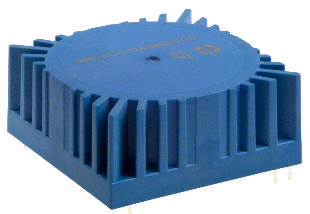
Another option is a low voltage toroidal transformer. A good example is the Amveco 70050 rated at 10VA [link]

The basic hookup of a transformer to the DAC is as follows:

WARNING: AC MAINS voltage can cause death. If you don’t know what you are doing, don’t handle mains voltage.
DC Supply Hookup
The basic supply would be a bipolar +/- 12V supply. A low cost 78xx/79xx-based regulators would be good step up from a transformer-only supply
Note: the on-board bridge rectifier is a fast/soft switching bridge and a low cost DC supply comes with standard diodes/bridge – you may be trading off regulation with increased high frequency noise.
You can find plenty of adjustable supplies on eBay for very little money:
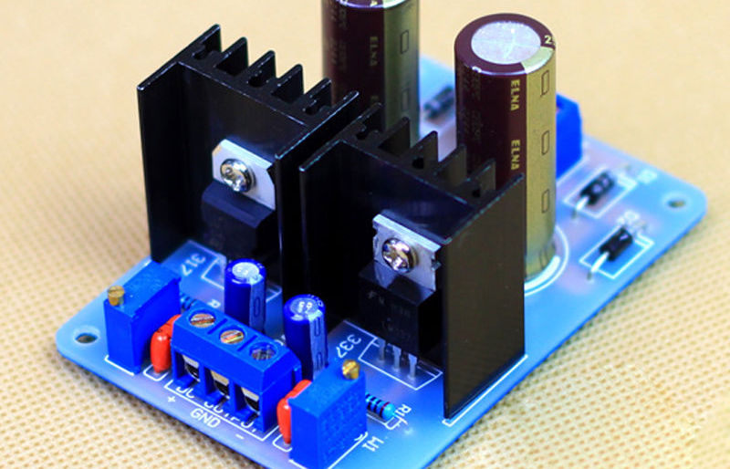
Or better yet, get a higher quality one from diyinhk which includes name-brand components:

The basic hookup is as follows. Notice that if you use a regulated supply, you need to increase the voltage of the transformer. A rule of thumb is to use the same AC voltage as the DC voltage.

Users have reported improvements from using a regulated supply over a transformer only supply [link]
…We started with the DAM as it was, with the Salas BiB (low noise regulated supply). We then unplugged the Salas and hooked up the plain transformer.
The change was immediately obvious. The sound thinned, it became more harsh in the high end. It also lost resolution and detail. Going back to the BiB made all the good qualities come back.
FIRST TIME POWER ON
Turn the power on and measure the voltages through J2 to ensure proper operation:
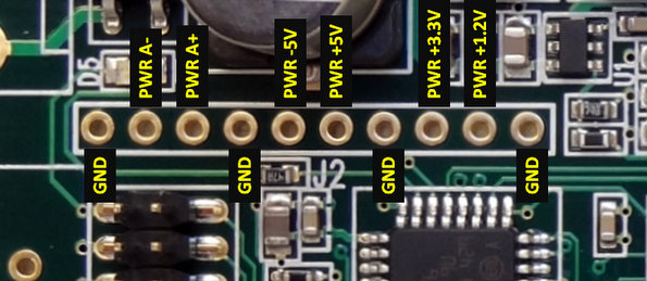
The analog power: PWR A- and PWR A+ depends on your input voltage. For a DC value of 12V you will see approximately 11V because of the voltage drop in the bridge rectifier.
SOFTWARE INTERFACE
Like many modern DACs, the dam1021 has a software interface. You can control the DAC with a micro-controller or a PC, update the firmware and upload custom digital filters.
In most DACs, the communication protocol with the DAC is I2C. In this DAC is serial communication. The dam1021 has two serial interfaces:
- Noise isolated TTL-level serial (not enabled as of this writing)
- RS232 serial (enabled with first release)
Communicating with RS232 Interface
Also check dimdim’s blog which has an excellent writeup on the RS232 interface [link]. Here I document my own experience with the interface.
You need:
- PC serial port
- Or a USB to RS232 interface cable capable of supporting 115,200 baud
- Note: The serial port transceiver on the dam1021 R-2R DAC has power savings enabled, to reduce noise. It needs valid RS-232 level on the RXD line to power up. If your USB-Serial dongle also have power saving then you have a problem. [1176]
- Terminal program
Hardware connection
Connect the RS232 pins to the PC serial port as follows. This is basically a null-modem connection without h/w flow control. You may want to check this informative site on serial communications including RS232 [link]
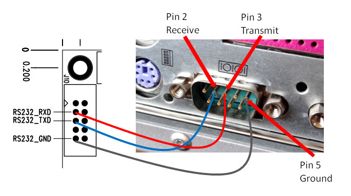
I made a simple 4-feet cable with 2 twisted pairs of cat-5 wires.
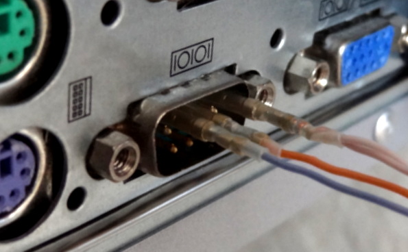
Notice the pins in the board can also be numbered 1-5 counting from the top right in the photo. So pin 2 in the PC serial port goes to pin 3 in the DAC, pin 3 to pin 2 and pin 5 to pin 5.

One can interface with the DAC in two modes:
- Interactive by invoking the “uManager” and using a terminal application
- Non-interactive by sending messages to the DAC through the serial port (with or without a terminal application)
Using Terminal Application (Tera Term)
The terminal program must support xmodem file transfer protocol. Putty is a very popular terminal program but does not support xmodem. “ExtraPutty” is an offshoot of Putty and supports xmodem, but it requires .NET but I didn’t want to download .NET. I ended up selecting “Tera Term”. Check the use of ExtraPutty in dimdim’s post [link]
Download Tera Term from [link]
After downloading and extracting all the files, launch the application “ttermpro”

After launching Tera Term, select “Serial” and select the Port you are using to communicate with the DAC.

Configure the serial communication parameters with:
- Baud rate: 115,200 (This is pretty fast. Use a good, short cable)
- Data bits: 8
- Stop bits: 1
- Parity: none
- Flow control: none
Click on the “Setup” pull-down menu and select “Serial port”

Invoking “uManager” for Interactive Mode
Type “+++” and wait for the DAC to respond (~1 sec). You must enter “+++”, otherwise there will be no response. If you enter anything else, there will also be no response. “+++” invokes the “uManager” enabling interactive communication with the DAC through a terminal window. The DAC also responds to commands sent through the serial interface (more of that later)
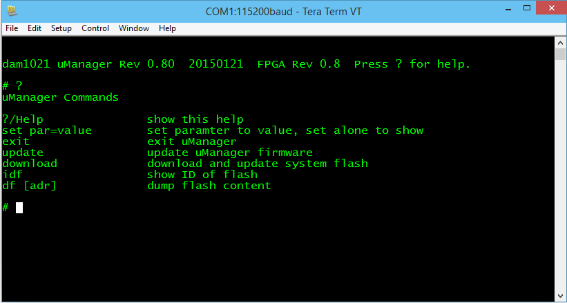
The dam1021 will respond with the following screen. Notice the original firmware is “FPGA Rev 0.8”

Typing “?” returns a list of available commands
Updating the firmware
First download the firmware from [1116] and unzip it (it is a “SKR” file):

Type “download” in the terminal window. The DAC will acknowledge your command and wait for you to start the xmodem transfer.
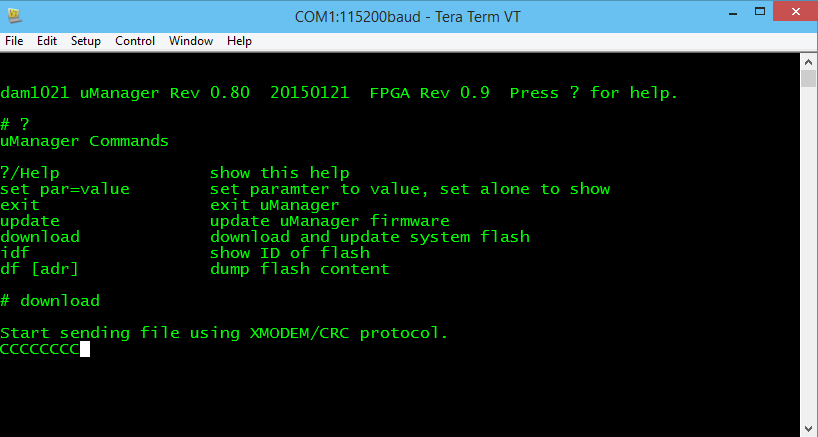
In the “File” pull down menu select “Transfer” -> “Xmodem” -> “Send” and you will see the XMODEM send dialog box. Select the file you downloaded and click “Open”

The file will start transferring and you can see progress in the progress bar.

After completion, [optional – type “exit” in the terminal window] power cycle the DAC. Type “+++” in the terminal window and wait (~1 sec). You will see the following screen. Notice that the firmware version is now 0.9

Non Interactive Commands
You may send commands to the DAC through the terminal application but without invoking the “uManager”. If you are in uManager, type “exit” to exit uManager. The DAC is then ready to receive messages/commands.
UPLOADING DIGITAL FILTERS
Now that we know how to update the firmware, uploading digital filters uses the same procedure. Lots of filters have been crafted by users in the diyaudio filter brewing thread [link]. Filter files ready to be uploaded are binary files. The filter text files cannot be uploaded. They need to be converted to binary format with the “filter tools” provided by Soren [link]
The procedure for uploading a filter file is hereby summarized:
- After invoking the uManager, type “download” in the terminal window. The DAC will acknowledge your command and wait for you to start the xmodem transfer
- In the “File” pull down menu select “Transfer” -> “Xmodem” -> “Send”. You will see the XMODEM send dialog box. Select the filter file you wish to upload and click “Open”
- After completion, power-cycle the DAC. Note: changing the input or changing a track with a different sample rate also triggers reloading of the filters
MASTER CLOCK OUTPUT
Ref: [848]
- I2S MCLK OUT pin: Master clock output: 45.1584 and 49.152 Mhz (which can also be divided)
- I2S FSEL IN pin: Input signal at this pin selects between 45.1584 MHz and 49.152 MHz master clock output
Although not advertised as working with the initial firmware, it has been reported to be fully working as indicated above. [link]
MY OTHER POSTS ON THIS DAC
| TITLE | SUBJECT |
LINK |
DESCRIPTION |
| Soekris dam 1021 R-2R DAC ILLUSTRATED GUIDE | Users Manual | [link] | Users manual for the Soekris DAC. |
| Soekris dam1021 Build | Build Guide | [link] | Details of my initial build of the Soekris DAC. |
| dam1021 R-2R DAC MODs | Mods | [link] | Mods I have performed on the DAC build. |
| dam1021 R2R More Mods | Mods | [link] | Later mods on the DAC build. |
| Digital Filters for Soekris R2R DAC | Digital Filters | [link] | Extensive list of DIY filters from the diyaudio filter brewing forum thread. |
| R2R Benchmark Filters (for now) | Digital Filters | [link] | Latest set of filters developed and shared in the diyaudio filter brewing forum thread. The best filters of the bunch. |
| R-2R DAC For The REST of US | Technical Details | [link] | Introductory post describing the innovations and capabilities implemented in this DAC. |
| The Soekris R-2R DAC: Technical Details | Technical Details | [link] | Additional technical details of the Soekris DAC that were not covered in the post above and collected after I had the DAC on my hands. |

Very very nice work as always, glt! 🙂
I have noticed that you are suggesting that the isolator’s power supply’s GND be connected to the Soekris’ GND (the main one, not the isolated one). That doesn’t sound right to me. As a matter of fact, it shouldn’t actually work. Are you sure about that?
Hi dimitr, you are absolutely right. I had made a mental note about it but forgot. Will correct the diagram. Thanks.
Fantastic work!
One thing I don’t understand about isolation between I2S lines.
I use my board without external power applied to ISO +3.3V and ISO GND.
How come it works? Or does it mean that it works without isolating?
I actually haven’t realized this until I read this post!
It is not very convenient that we have to add a transformer+rect+filter+reg just for this.
You could use the power and gnd from your usb i2s adapter. Actually without any power, just the i2s pins from a powere usb, the isolator power pin shows ~2.5 v. Ill have to do more looking to figure out what is happening…
Any update on this? I too don’t have +3.3v ISO PS and it works fine, but worry that may cause some damage? Also really can use +5V instead? Thanks
Yes, can use +5V
Hi, thanks for your effort and time… Only one thing, you dont need to turn off first the amp and then the dac? Thanks again…
Yes… Let me see what i wrote…
Nice write-up and organization. Thanks for all your time and efforts
Many thnks for such tremendous work!!
Thanks for the all-in-one-place reference – great job as usual. In messing with changing volume via the serial connection I inadvertently disabled the pot controlling the digital volume. After spending considerable time wading through the various threads in search of a remembered post by Soren where he mentioned how to enable the pot I found it and got the pot going again. In the spirit of all-info-in-one-place it might be an idea to add the commands to the serial section of your Guide: ‘set volume = xx’ disables the pot and ‘set volume = -99′ re-enables it.
Also, it would be nice to have the specs on the buffered output included in the Guide. Think they were something like 4V, 20R on the balanced and half that if you just used the hot side. But that’s from memory – which is why it’d be nice to have ’em in one place… ; )
Hey Derek, thanks for the tip. I actually changed the volume setting last night and didn’t change it back. I would have never figured that changing the setting to other than -99 would disable the pot volume control.
Yeah I have the output impedance data in another post. Will put it all together. As useful as the blog is for all the readers, it is even more useful for me because I know (most of the time) where everything is. Using Google and adding “hifiduino” to whatever term will usually return what you are looking for because “hifiduino” is unique. This was a great benefit after the fact…
Hi BigGear,
Do you think there will be a problem for sound quality if:
– AC supplies not exactly the same? (for example one is 7.5 and one is 7.9)
– Ground point is not middle tap
My setup now is working great, but I still “tactic” in my head when I still unsure thing as above
Thanks for your great guide! Thanh
The only parts that are “affected” are the output buffer opamps. The digital parts would use the positive supply independently, the reverence voltage use separate regulators to derive the +5v and -5v, so no problem with those parts. There would be a problem with the opamps only if you run them to clipping voltages, but they are not. Check this thread: http://www.diyaudio.com/forums/parts/133324-lop-sided-supplies-opamp.html
Thanks a ton, BigGear!
Hi, It seems you drew you’ve linked the DC external power supply to the AC connector on the DAM…
Yes. You can feed AC or DC through the same connector.
glt, my understanding is that mono mode will use the “left ladder” for + and “right ladder” for – of balanced signal. In this config the unbuffered balanced output would use J7 with pin1 as + and pin4 as – for example. I’m assuming the firmware update which enables mono will take a single channel input and and invert this to give the +/- components for conversion, rather than doing channel assignment to left or right. It’s a long winded way of saying “don’t expect mono mode to bring channel swapping to the DAM”.
cheers
Paul
Haven’t thought about it too much, but seems a trivial matter for an FPGA to do channel assignment and channel phase. If the FPGA is capable of taking the incoming data for one channel and sending it off an output, then it should be possible for sending it off another output (since it is just internal code). In the same manner, if the FPGA can separate positive values from negative values and send them to their respective outputs, then it is just a matter of swapping the output pin assignment in code.
It might require uploading a configuration file or a section in the filter file with configuration options.
But I am OK with changing labels 🙂
Actually with a bit more thought, the Mono mode will need to enable FPGA communication between two boards to work, as one board will need to be “master” to handle channel splitting between boards. I still think channel swapping per board is unlikely – and really it is just a matter of swapping the labels on the case to “fix” the “issue” 😉
Great web site you have got here.. It’s difficult to find excellent writing like yours nowadays.
I honestly appreciate individuals like you! Take care!!
very nice, how would I go about wiring up an balanced i2s hdmi output into this dac?
https://scontent.xx.fbcdn.net/hphotos-xpa1/v/t1.0-9/11175044_10155508613875022_452139098465150190_n.jpg?oh=82c46641b501461a9f13bb2df374a318&oe=55E06F05
Just wire the + terminals (you may ground the – terminals with a 10K (or so) to GND)
> DC: +/- 7 to +/-15V DC; preferable 9-12V DC
Actually I don’t understand that 9-12V DC recommendation. If this board was designed to operate on 7.5-8V, what is purpose of feeding more V than needed, besides generating more heat?
It works within that range of DC voltage input. You may feed AC voltage in the 7.5-8V range.
DC: +/- 7.5V DC to +/-15V DC; preferable 9-12V DC
AC: dual secondaries 2x 7-8V AC or center-tapped 0-16V AC
Great guide! One thing regarding the master clock and FSEL. It does not work on latest 0.99 firmware version. So the MCLK is only transmitting a 24.5764MHz signal with no change whatever the FSEL is (LO/HI/NC). As stated in #3817, #3829, #3832 on the diyaudio thread. So playing 44.1KHz and its multiples will result in playing in a slightly higher pitch. All other things considered beaglebone with botic5 driver seems to work perfect with no need of capes.
Hello folks! Just want to leave a comment and a question:
– I’ve just upgraded my DEQX PDC with Soekris R2R DAC and I’ve become a fan instantly, even without the numerous mods recommended ;o)
– One thing is a little diturbing: As I’m listening to different Audio file resolutions, the DAC has to resynchronise when changing resolution / sample rate. Soekris does this with a clear announcment, a very lour “crack!!”. If anyone knows of a muting possibility, i.e. until the “crack!!” is over, that would help me (and at least a few others) a bunch! Thanks for responding!
Cheers to a great DAC anyways!
I know this reply is late, but update the firmware to the latest. Soren done a lot of work to fix those loud cracks. I’m unable to hear a peep out of mine when changing sample rates with the latest 0.99 version. He did a few updates since the original v0.99 was posted.
Have any of the connections changed on the v3 board? Thanks!
Firmware 1.04 is out ! 🙂
Anyone hear from Paul lately? He’s been quiet on his blog nor has he been posting any user comments for over 2 months. Did he quit on the dam front? Was hoping he could continue the filter research now that the FIR2 bug is supposedly fixed in 1.04. Would be great if his latest “grab bag” filterset was updated to include the new DSD filters.
Hi, i used this guide extensively. Dam1021 can’t get a lock with amanero adapter. Using dedicated regulated 3.3v supply instead of amanero 3.3v. Using twisted pairs under 6 inches long. Same problem on both Win and Linux. OS sees amanero board, so I assume problem is between amanero and dam1021.
Dam1021 voltage supplied by reg volt power supply at +/-10v (plenty of current available). Tried 4 usb cables, one is StraightWire; is good quality. Only time it locks (sometimes) is from a power off, unplug power, the boot up. As soon as the OS loads, it unlocks.
Any ideas where I can check for problems? Was going to buy jlsounds and diyinhk i2s adaptors, but before I do I’d like to see if someone has any advice. Soekris support is limited.
Thanks, vince
Problem was the Amanero I2S board needed to be flashed with updated newer firmware.
Once done, it connected to both Win and Linux music servers. Firmware available at Amanero site.
How can I obtain this unit and how much will it cost?
Regards
http://soekris.eu/shop/dac_modules_diyline_dam1021_en/ if you are in Europe or http://soekris.com/products/audio-products/dam1021.html for the rest of the world
Zurich Private Capital
netflix account
nature’s comfort reviews
swiss watches
koraliki do bizuterii
wordpress metro themes
Best Dance Music
That is really attention-grabbing, You are an excessively professional blogger. I’ve joined your feed and look ahead to searching for more of your wonderful post. Additionally, I’ve shared your website in my social networks!
Hi, thank you for this paper. I wanted to build a battery supply powered DAC and dam1021 is exactly whar i needed.
Are the info here ok too with the OEM 5v one ?
Excellent write-up. I absolutely appreciate this site. Keep writing!|
I am not even kidding, you are so thoughtful. Thanks for posting this great blogs.
I am really enjoying the theme/design of your blog. Do you ever run into any web browser compatibility problems? A small number of my blog audience have complained about my website not operating correctly in Explorer but looks great in Safari. Do you have any suggestions to help fix this issue?
I am using the diyinhk regulated power supply you have pictured in this guide. Just as pictured in your blog, it’s got two 12VDC outputs. Do I connect only one of the 12VDC outputs to the Soekris?
Hello there!
You Need Leads, Sales, Conversions, Traffic for wordpress.com ? Will Findet…
I WILL SEND 5 MILLION MESSAGES VIA WEBSITE CONTACT FORM
Don’t believe me? Since you’re reading this message then you’re living proof that contact form advertising works!
We can send your ad to people via their Website Contact Form.
IF YOU ARE INTERESTED, Contact us => lisaf2zw526@gmail.com
Regards,
Weeks
hi, im using tera term 4.104 on xp, and the voltages at my usb-rs232 adapter ( star tech icusb232v2) appear correct (0 and -9v) but i cant connect to the dac (dam1021). i type +++ but the characters dont show correctly and instead are some garbled characters. any solutions ? much thx 🙂
Can you tell if it is possible to implement 3x of the dam1021 in the DEQX to obtain the possibility to use the 3way active crossover funtion in the DEQX?
Awesome guide and resource! Thanks for your efforts to write this up!
I’m picking up a DAM1021 this week and this info has been very helpful for when I start hooking everything up. However, I have a question that I’m hoping you can help me with. I already have an IanCanada Streamer with the FiFoPi and Relocker. My question is being that the DAM1021 has a built-in FiFo and reclocker, do you think I can still run my streamer like this?
Hi, can someone help with the 2541? I set the volume to fixed I think, and now the device boots up with 00db instead of -40db like before. I’ve tried: set volume = -25, set volume=-25, set volume -25, set volume = fixed -25 but nothing worked.
Also, is there any news for the 2541 custom filters?
Thank You for a very detailed manual it is really really valuable.