BUILDING THE DIYINHK ES9018K2M
I have come to the realization that audio diy never ends. There is never the “final” project. There is always tweaking, a new mod, new stuff. Thus I decided to use a cardboard box as an enclosure. Much easier to work with, simple tools would do.
Many would consider a proper enclosure a must for a diy project, but for me this is good enough. Here is a nice looking Lenovo tablet box.

POWER SUPPLY TRANSFORMERS
Three separate transformers were used:
- DAC supply transformer: salvaged from an VCR from the time that linear supplies were still being used. These transformers are very nice, having at least 2 hefty 9V secondaries. The secondaries feed a TPA dual PS which is used as a pre-regulators for the DAC supplies. The two capacitors hanging off the transformer provides DC to an LED (to indicate power 0n/off)
- Analog supply transformer: 15×2 toroidal transformer. (Got it from Twisted Pear Audio)
- Controller transformer: 6V DC salvaged from a wall-type supply, upgraded the smoothing capacitors


Water bottle caps are perfect for the feet.

DAC AND ANALOG SUPPLIES
Used a quad-supply board. This board is designed to provide 4 x 3.3V/5V regulated output. Two supplies receives pre-regulated DC, two supplies receive AC (thus the larger filter capacitors).

Two of the regulators were modified to provide 14.2 V (1.4V+6.4V+6.4V) for the opamp by shorting pins 4 and 5 to GND. They are also configured to provide +/- 14.2V by tying the +output of one of the regulators to GND (I followed what diyinhk did for their dual +/- supply [link])


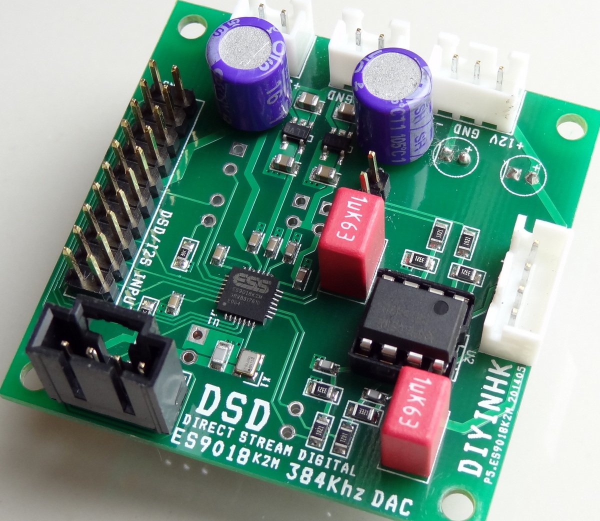
DAC BOARD
Standard build. Only “upgrade” are the electrolytic capacitors. On the backside, the jumpers are to connect the I2C lines to the separate I2C header because I forgot to short the lines on the front side before I soldered the connector (which blocked the jumpers). Later I will upgrade the opamp.

There is a separate SPDIF input connection that feeds the GPIO2 pin in the DAC. Selecting this GPIO pin for SPDIF input has been enabled in the code.
GPIO1 is configured in the board to be in input selection pin for manual selection of I2S/SPDIF. My code does not enable this mode because the selection can be done directly through the user interface. This is here for manual selection with a switch and requires that the chip be programmed in such a way. I believe the diyinhk XMOS interface would program the chip to allow manual selection of SPDIF input.

The board comes with an NDK 80 MHz oscillator [link]. Other implementations may use a 100MHz clock. The software support both 80 MHz and 100 MHz clocks.
In addition, a separate supply can be used to power the clock by cutting the power trace and connecting the supply to the through-hole vias.

ANALOG AND DIGITAL POWER
The external 5V powers a single regulator for the analog 3.3V AVCCR and AVCCL. . The second regulator provides 3.3V to in chip internal oscillator (I think in order to support an external quartz crystal instead of an oscillator). The regulators are marked “LLVB” and are TI LP5907 Ultra Low Noise regulators for analog applications [link]. They rank near the top among ultra low noise regulators [link].
The external 3.3V is used directly without further regulation to power the digital side of the chip and also the local oscillator.

Power to the oscillator is further filtered by a ferrite bead

OPAMP POWER
Positive and negative supply voltage are taken directly to power the opmap.

OUTPUT
The board has connection for the differential outputs straight out of the DAC chip and also single ended output through the opamp. I am using the single ended output wired to a mini-plug for connection to a headphone amplifier. The opamp provided is a NE5532 dual operational amplifier [link]


GROUND PLANE
Nice, solid ground-plane

ALL TOGETHER


Very creative I just hope you don’t have a fire 🙂
You have a point there 🙂
Hi, I’m interested to know how it compares to the orginal ES9018 (the buffalo or QuangHao’s), did you compare them soundwize? Have myself a (it seems not too bad) implementation of the ES9023 and am looking for something to challenge it with 🙂
I have not done a one-to-one comparison. The K2M is set up with headphones. The other DACs are in my main system Spec-wise, the new chip is a single DAC pair whereas the older ES9018 uses 8 DAC pairs and thus has better numbers. The new chip has better features such as a new filter, ability to receive 16-bit data (as in taking the data from a cd rom). The registers are better organized.
I would guess the new chip is the follow-on revision to the ES9018 but aimed at the high volume market.
hello,
I would like to create a portable player for .wav/flac mp3. like http://head-direct.com/Products/?act=detail&id=158 ( well a lite version of course)
In your project it is not said where comes the data from. does the arduino only provide volume/ lcd info ? do you need to connect the es9018 board to an USb board? (like this one : http://www.diyinhk.com/shop/audio-kits/63-isolated-xmos-dsd-dxd-384khz-high-quality-usb-to-i2sdsd-pcb-with-ultralow-noise-regulator.html )
do you think its possible to read wav files fom sdcard via arduino and have it process with the es9018 , then use OPA627 ( they use 3 per channel on the Hifiman product) to headphone out?
also dont you have a schematic of your device? It’s hard to figure out how the es9018 is connected to arduino etc only from pictures.
thank you.
Yes, the Arduino wit the supplied code only controls the features of the DAC chip. You need to connect a source to it through its I2S or spdif interface. There are Arduino solutions to play sound files stored in an SD card, but it is beyond the scope of this project.
Like the box concept -beats Perspex in terms of carving it up!
I have one of these K2Ms from DIYINHK along with the ‘modified for bit-perfect volume control’ XMOS USB-i2S board. Works fine with both Voyage MPD on an Alix 2d2 and Volumio on a Raspi except that I cannot get the volume slider in mPod to control the volume. I have tried altering mpd.conf in various ways but the only way it works is if I enable ‘software’ mixing – which is not how it should work, I believe.
What am I missing?
PS I sent you a pm on diyaudio with more info.
Hello! I just buy DAC ES9018K2M from diyinhk and I want to connect bi to the Raspbarri Pi (with Volumio) trough I2S interface (only 3 wire + gnd, without Masterclock). How do you think, it will be work?
Do I need to use in this case “ADDR” and “SDA, CSL, GND, 3,3 V” cintacts on the board?
The pins you mentioned are for the I2C interface to control the DAC.
Hi GLT,
A good project that is not expensive.
I just have one question.
Buono R3 has a variety of power system 3 volts or 5 volts.
If it works in 3 volts then you do not need level converter?
Yes, but unfortunately all low cost LCD displays are specified for 5V operation. It also “appears” that the DACs are 5V tolerant according to some reports, but the datasheet doesn’t explicitly says so, so better safe than sorry.
In the FAQ it says “The SPDIF input(labeled SPDIF IN) signal level requirement is 3.3V”
is there a schema for such a device?
You use a comparator such as this: http://www.ti.com/lit/ds/symlink/lmv7219.pdf . An example implementation can be found in the Buffalo DAC: http://twistedpearaudio.com/docs/digital/buffalo_schematic.pdf
How much is the powerconsumtion on the digital and the analog side (3,3v)
Hi
Im gona star new dac build soon. And wonder which board shall I use . How does it compare to Twisted ES9018, or Audio design guide . Its obviously half the price, but is it competitive with this two ?
Depends mostly on your budget and the urge to keep upgrading. If upgrading is something you like to do, then get the TPA board. As I said earlier, I have not done side-by-side comparison.
I have the same diyinhk board. Do the DAC chip and the board also have current output?
My analog part can handle both voltage and current output DACs. I’m curious which one is sonically better, if the DAC/board supports both modes.
The datasheet indicates that it can be used in current out or voltage out mode. The spec does not say which mode performs better. The older ES9018 DAC performs better in current out mode.
Great information, thank you for the reply.
I have bought a Lampizator Amber, containing this diyinhk board. The documentation of the analog part tells how to switch the tubed analog part to current mode (means to higher gain). But I have no documentation of the DAC chip, nor the DAC board, how to switch to current output mode. Can you tell me how to do it? If possible, a documentation of the digital part is also wellcome. As far as I read on the web, this chip has excellent digital volume control, and other usefull features.
The DAC can work as current out or voltage out at the same time. No changes/settings are necessary. The DAC will work in voltage mode if a high impedance is presented at the outputs and in current mode if a low impedance is presented at the output. Basically in current mode, the voltage at the output is kept more or less constant and the signal is modulated by the current output.
The DAC’s internal features can be exposed through s/w as explained here: https://hifiduino.wordpress.com/2014/06/30/es9018k2m-code-fully-tested/.
Looking at some of the photos of the Amber DAC, it looks like the volume control is done with resistors and relays after the tube stage (this actually is good as it keeps a high output to the tube stage and attenuates both noise and volume after the tube stage).
Yes, the Amber is available either with an analog volume control, or without any volume control. Fortunatelly my device has this remote controlled attenuator.
This site
http://www.diyinhk.com/shop/audio-kits/60-usb-dsd-dxd-384khz-dac-with-bit-perfect-volume-control-and-spdif-inputxmoses9018k2m.html
says they have the first really good digital volume control. Interesting, never heard a good digital attenuator before.
I’m just curious to the difference of the analog vs digital volume control.
Thank you for clearing how use the DAC in current and voltage mode.
The device shown in the link is a USB inteface that can control the DAC’s internal digital volume control. The USB inteface driver translate the operating system volume adjustment into signals that are passed to the DAC through its I2C interface allowing the DAC to control the volume in the digital domain. It is no different than controlling the DAC with a microprocessor but just more convenient and simpler (since you just use your PC to control the volume)
The diyinhk site above contains a further link explaining the DAC chip’s internal digital volume control:
Click to access digital-vs-analog-volume-control.pdf
So the question really is (for me at least), how good is the DAC’s internal digital attenuator relative to this
http://diysoundlab.com/index.php/vc-03-volume-control
analog control?
Hi,
Now I’m trying to control DIYINHK ES9018K2M board by your Version K2M05 code,
but not recognize the dac board, display shows ‘- not k2m -‘.
I’m checking wiring but no mistake.
Any advice for me?
P.S.
I find out maybe mistake at line 433 of your code, missing ‘;’.
Thanks!
Hi, i also build this dac and measure not exact 12V+- for the opamp. Diyinhk says no problem but not sure to be honest. I use the standard DIYINHK 12V board. OPAMP is a LME49880
Any suggestions? Just listining against a SONY X559ES direct and through the DAC. Direct sounds better at the moment.
Addition to the post: The Dac is connected to DIYINHK USB XMOS ISOLATED and trhrough SPDIF
Hi,
Could you have a look for me please in the product description page for DIYINHK ES9018K2M it states;
“*When the ES9018K2M PCB used with our customized I2C control firmware XMOS USB PCB, extra features include a simple jumper(labeled SPDIF ON) to switch between SPDIF(labeled SPDIF IN) and USB input, bit perfect volume control as well as DSD/PCM playback in foobar without the need to switch ASIO driver everytime.”
What do they mean by the “jumper” is there automatic switch by connecting Optical and USB? or a some sort of manual slider etc.?
Thanks
It means that if you use the XMOS USB, it programs the chip (the DAC) to have manual selection of spdif by using a switch
Hi,
I am making a test build and everything is working well apart from the IR remote control. None of the buttons on the apple remote seem to have any effect. I have tested the IR sensor with an LED and it lights when buttons on the Apple remote are pressed so I know that the sensor is working, I have it connected to pin 3 on the arduino and am using the same Buono R3 as shown in your build. I have run out of ideas on how to get it working. Do you have any troubleshooting ideas I can try? Everything else works so well it would be a shame to no get the IR working.
Thanks
women timberland boots
preppers gear
Hi,
Still about the digital bit perfect volume control : are there parameters to set on player side ? (I use etalon linux base streamer with squeezelite). How does the player knows there are volume control data to send over usb ?
Thanks,
My brother suggested I may like this website. He was once totally right. This put up truly made my day. You cann’t consider just how so much time I had spent for this information! Thank you!