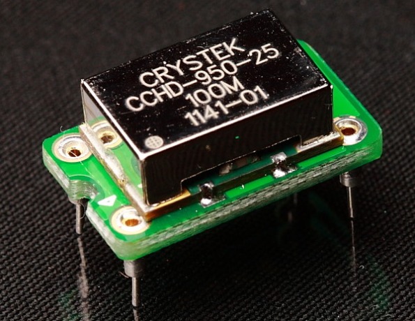
Crystek CCHD-957
Here is the new Crystek Oscillator which is tailored for audio applications (my own device and photo :-))
According to this, here is the crystal inside a Crystek CCHD-957 module (which was used to mod an XMOS board)
Lets take a peek inside the clock unit.
Peeking inside from one side of the clock module. (I am not going to remove the metal shield. This thing costs over $30 🙂 )
Peeking through the other side of the clock module. Indeed there is a can crystal inside the clock module as reported.
Just the basic components for a Pierce oscillator?: capacitors, resistors…
and a digital inverter?
More photos. I took these with a high intensity LED flashlight and set the aperture way down to get larger depth of field.
The following two photos on the same side of the clock module, but different angle…there is another integrated circuit/transistor on the other side (see left side of first photo) …
Another view of clock module, this time the can crystal is more clearly shown.
Shining the flashlight through the PCB.
View from the other side of the module
Jitter values compared
Comparing the specification of the CCHD-957 with the CCHD-950-80 (which I have on the Buffalo II DAC) we find a “huge” decrease in jitter RMS (as calculated with jitter calculator)
Impressive reduction of jitter (but can anyone even hear 2 psec jitter?) In any case, this new breed of high performance clocks does not cost any more than the older CCHD-950 versions, so it is a very welcome improvement. Plus the fact that they are available in frequencies tailored for audio applications makes them even more suitable/desirable.
Use in Ian’s FIFO board
I plan on using this oscillator in Ian’s FIFO Jitter eliminator. The clocks included in the kit are the “generic” types and are included for checking the baseline functionality. They are also of lower frequencies.
Using this frequency provides support for all sample frequencies
| Clock F |
44K/48K | 88K/96K | 176K/192K | 352K/384K |
| 45.1584MHz / 49.152MHz | 1024Fs | 512Fs | 256Fs | 128Fs |
| 22.5792MHz / 24.576MHz | 512Fs | 256Fs | 128Fs | Not supported |
| 11.2896 MHz / 12.288MHz | 256Fs | 128Fs | Not supported | Not supported |
Is 40-50 MHz optimal?
For the Sabre DAC, it seems that it “likes” having a master clock in the 40 to 100 MHz. Since the FIFO needs frequencies that are multiple of 44.1KHz, and the Sabre32 “likes” frequencies above 40 MHz for the master clock (not sure if this is a requirements, but all implementations seem to use frequencies of 40 Mhz, 80 and 100 Mhz), this clock at 45.1584 MHz seems to be optimal for interfacing the FIFO to the Sabre32 chip in the Buffalo DAC.
The following arguments may indicate that this frequency range may be optimal for the Sabre32 DAC
According to Dustin [link]:
…by the way, running the DAC at 80MHz with a good crystal you can expect to only see a 1dB DNR loss from the 40Mhz boards, if that. Some show no diff, some showed 1dB.
In addition, the power requirement of the analog supplies (AVCC) with the lower frequency is about 40%-50% less [link] resulting in a cooler running electronics.
Example of some implementations also show the use of 40-50 MHz frequencies:
The $32K Accuphase DC-901 uses a 40 Mhz clock
The Resonessence DAC uses a 50 MHz clock [link]
Both analog boards are preceded by a Crystek CCHD-950-20 low-phase noise clock. We chose the 50MHz part as it has the lowest phase noise at offsets that are in the audio band. The clock has its own dedicated ultra low-noise power supply
Historically, the frequency of the on-board oscillator has been moved up from 40 Mhz, to 80 Mhz and then to 100 Mhz.
The evaluation board from ESS is designed with a 40 Mhz clock. The desire to support 192K sample rate, moved the frequency to 80 Mhz. Then playing 352Khz material, required moving the frequency to 100 Mhz.
Mounting the Clock
Since these are SMD parts, one needs to first mount them in a suitable adapter board. At first I was thinking of crafting something myself, but one can now buy adapter boards from Ian such as this:
Other diy projects
An interesting project using CCHD-957 clocks in an XMOS board is this one by “Viper2001” over at head-fi (and also here: link):


Hi..
If there would be edit possibility I would change my previous message from “almost artistic” to just artistic pictures… 🙂 …
My 2 x CCHD957 are stuck at the custom… 😦
Rosendorfer
Hi Rosendorfer,
No worries :-). Please report back on your experiences with the 957. The new TI regulators seems a good match for these clocks. They are the lowest noise part available. Since clocks are a constant load, there is no real need for shunt type of regulators.
Hi
“Since clocks are a constant load, there is no real need for shunt type of regulators.”
Well that is technical fact, but again, even I with my far from golden ears, could heard “improvements”/change on My Buffalo II when using of-board Clock PS. … ;).
Will see in next week if I will be able to hear difference between TentLabs and CCHD957 XO’s.
But have to say, that CCHD957 XO’s are “baldy” expensive, hope they are worth their price…
Would feel much more confident if we knew PS Crystek have been using doing their nice looking Jitter measurements. Without more details and also independent measurements on real XO’s samples we easily could be in bit different place that we all hope to be.
Rosendorfer
Hi Rosendorfer,
I am glad there are those with discerning ears in this hobby. I have to go by numbers. Keep us posted on your experience with the 957s.
nky real estate
hotel gdynia
Where I can buy adapter?