iTeadStudio TFT Display for ARDUINO
INTRO
Purchased a 400×240 pixel graphic touch-capable display (new link) module plus its accompanying Arduino MEGA-compatible shield from iTead Studio. The shield has been updated to version 2. See bottom of post for more information.
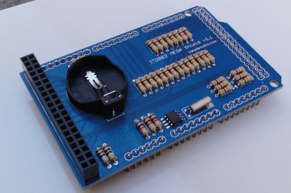
The shield has, in addition to the connections to the display module, connections to a battery-backed real time clock that has been implemented in the shield. The display module consists of the display panel (the screen), a touch controller and a SD Card socket.
The iTead description says:
The ITDB02 LCD module is work in 3.3V voltage level and it’s not compatible with Arduino MEGA pins, so we make a shield for Arduino MEGA. Now user can directly plug the ITDB02 in the shield and stand on the Arduino MEGA board.
In reality, the ITDB02 module IS fully compatible with Arduino MEGA pins. The shield just makes it much, much easier to connect to the Arduino board. With respect to the 3.3 power, the shield merely connects the Arduino 5V power pin to the display module’s VCC pin which feeds a local LDO regulator that generates the required 3.3V.
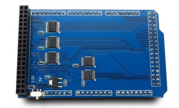
MEGA COMPATIBLE SHIELD
The real time clock: DS1307 I2C interface. A clock board alone already costs as much as the entire shield.
(Update 9/7/12): The resistors in the shield are there to limit the current to the protection diodes in the display module, so they are just in series with the signal lines. The inputs of the display must be 5V tolerant even thought the display operates at 3.3V. The better solution is to implement a level conversion 5V->3.3V and this has been done in the new version of the shield. More information in the Arduino forums [link]
COMPONENTS OF DISPLAY MODULE
Full color, 400×240 pixel TFT screen with a 16:9 widescreen aspect ratio. S/W supports 24-bit RGB color. The ITDB02-3.2WD uses the HX8352-A controller
On the back side of the display module:
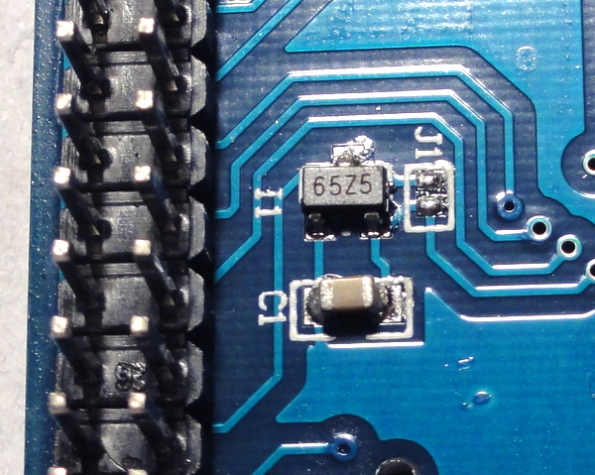
3.3v LDO regulator: CE6209. The jumper J1 is there to bypass the regulator if your VCC is already 3.3V. First time I see a Chinese-branded LDO regulator.
Note that J1 is used to pass VCC if a regulator is not used. In this case, a regulator is used and thus J1 is open. There is also opportunity to increase C1.
Touch controller: TI ADS7843 compatible: XPT2046
SD Card socket
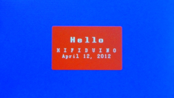
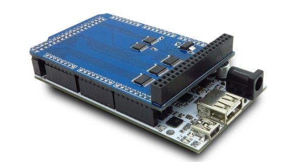
Here is the display module and the shield stacked on top of an Arduino MEGA 2560
SOFTWARE
Check out the latest libraries here: [link]
Screen:
The library (“UTFT” for “Universal TFT”) for this display has been developed by Mr Karlsen and is available here: [link]. Support for the 240×400 pixel display is available with version 1.10 and higher as this is a new display. The software also supports the wiring of the Mega shield shown above. (The control pins are assigned through s/w, though).
The controller for this screen is HX8352-A (apparently it replaces the ILI9327 controller). You will need to enter the controller model in the code as “HX8352A”. The enclosed documentation in the code tells you more. In addition, you need to know this controller model to take advantage of “memory saving” as specified in memorysaver.h
Touch control:
The library is ITDB02-TOUCH, also developed by Mr. Karlsen: [link]. Is also compatible with the wiring of the Mega shield shown above and any other wiring configuration as the 5 interface wires are assignable through s/w.
Real Time Clock:
Here is a tutorial on how to interface to the RTC device: [link]. Here is another using a library: [link].
SD Card:
Mr. Karlsen also developed a library for the SD Card socket/reader [link]. However it is limited to FAT16 formatted SD cards up to 2GB in size and 8.3 characters file names. There is also the Arduino SD Library [link] that supports both FAT16 and FAT32 file systems on standard SD cards and SDHC cards. It is also limited to 8.3 characters file names. There is also a tutorial on SD Card interfacing at LadyAda [link].
PINS USED
Even though the shield takes up all the pins in the Arduino MEGA board, not all the pins are used for the display module and the real time clock. You can connect other devices (e.g. soldering wires) to the free pins.
Pin-out assignment of display module
Includes the screen, touch controller, SDCard reader and Flash. Designation to the different device interfaces are as follows:
- Dxx: TFT screen
- SDxx: SDCard reader
- D_xx: Touch controller
- F_xx: Flash (not populated in this particular module)
Here is the pin mapping of the Ardino MEGA 2560 board:
Obviously the shield matches the 40-pin output of the display module with the pins of the Arduino. In addition, the shield has a real time clock that is separate from the display module and exports the interface pins of this device as well.
These are the pins that are used by the shield. You can refer to the pin basic pin mapping [link] and the manual in pdf [link] (I saved a local copy because this is now a discontinued product: ITDB02MEGAshield_DS ):
Shield/TFT           Arduino MEGA pins (section)

DB0 to DB15          22 to Digital 37 (Digital) - 16-bit data for screen
RS, WR, CS, RST      38, 39, 40, 41 (Digital)   - Screen control signals
LED-A, VCC, GND      3.3V, 5V, GND (Power)      - Power

SD_OUT               50 (Digital)               - SD Card reader
SD_CLK               51 (Digital)               - SD Card reader
SD_IN                52 (Digital)               - SD Card reader
SD_CS                53 (Digital)               - SD Card reader

------               42-49 (Digital)            - Free pins

D_CLK                6 (PWM -also digital)      - Touch controller
D_CS                 5 (PWM -also digital)      - Touch controller
D_IN                 4 (PWM -also digital)      - Touch controller
D_OUT                3 (PWM -also digital)      - Touch controller
D_IRQ                2 (PWM -also digital)      - Touch controller

RTC (SDA)            20 (Communication)         - Real Time clock (I2C)
RTC (SLC)            21 (Communication)         - Real Time clock (I2C)

Since the RTC is an I2C device, these pins can be used to connect other I2C devices
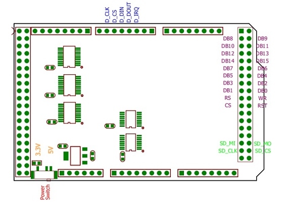
Here is a diagram of the pin assignments:
Note: a readier discovered an error in diagram for the SD pins. Look at the pin assignment in the following diagram from the vendor’s website. The diagram corresponds to the new V2 shield, thus there is no real time clock (which is an I2C device). However if you use the shield, you don’t have to worry about the pin assignments except to figure out which pins are free for other functions:
OPERATION
Download the latest version of the UTFT library.
Copy the UTFT folder to the arduino-1.0\libraries folder
There is sample code for the 400×240 display in the arduino-1.0\libraries\UTFT\examples\Arduino folder. Comment the code for UNO and un-comment the code for MEGA (follow the instructions written in the code). Modify the UTFT function with the model for your controller. For the above display I used “HX8352A”
// Uncomment the next line for Arduino Mega
UTFT myGLCD(HX8352A,38,39,40,41);   // Remember to change the model parameter to suit your display module!
Compile with Arduino 1.0 (does not work with earlier versions of the Arduino software and upload
Here is all I can for now…
(Update 9/7/12)
NEW VERSION OF THE SHIELD
The shield has been replaced with a newer mode. It does away with the real-time clock chip and replaces the resistors with logic chips (74xx541) for buffering and voltage level conversion, which is a better implementation. In addition it has a input voltage selection switch to make it compatible with Arduino (5v operation) or ChipKit (3.3v operation).
Possibly the buffer chip used in the new shield is a part similar to 74LCX541 which has 5V tolerant inputs and output. This design further protects the display module.
The resistors that were used in the previous version of the shield are there to limit the current to the protection diodes in the display module, so they are just in series with the signal lines. Based on the implementation of the shield, the inputs of the display must therefore be 5V tolerant even thought the display operates at 3.3V. The better solution is to implement a level conversion 5V->3.3V as implemented in the new version of the shield. More information in the Arduino forums [link]
Schematic [link]
The old version of the shield is still available in kit form: [link] for US $5.50. However it is missing the 3.3V regulator and the SD card reader (so maybe not such a good deal)
For some, this may be a better option because you can solder connection wires to some of the unused pins






Very nice, I want one of these to play with…
There is a new shield (v2) in the works…
I see that you too discovered the UTFT library!
I too have adapted my hifiduino to use the UTFT library to drive a 2.8″ TFT. However, I am having problems with the remote control. There appears to be some sort of conflict between the UTFT library and your IR code or between my 2.8″ TFT and your IR code (I was using adafruit’s 2.8″ TFT with their library with no problems, but now I am testing a cheap 2.8″ off of ebay with the UTFT library and seeing problems..).
Have you seen any similar behaviour in your case?
Hello, what kind of problems are you seeing? I have not integrated my display/Arduino MEGA with the code yet. Mostly just playing with the library code. LCDs are “noisy” even at the IR region. If you are seeing the remote “operating by itself”, try moving the IR sensor away from the display
It’s not that it is “operating by itself”. What happens is that when I point the remote at the sensor and send a command, every time I press a specific key the code reads a different (wrong!) value. It makes no sense. I have written into the code a couple of lines that display the remote code and I see it changing constantly, even though I am pressing the same button.
While troubleshooting, I tried running some other IR code on the same arduino, with the TFT connected, and everything seems to be OK. The trouble appears to begin when the TFT gets initialized.
Btw, my (well, actually “your” :p) code should run with almost no modifications on your mega + tft. Would you like to try it out and see for yourself?
I just tried using pin 11 instead of pin 9. Same behavior.
Hmmm… Don’t know. I guess I need to try it myself. Not much spare time these days…
My latest news are as follows. I replaced the problematic 2.8″ TFT with one like the one that you have purchased, and it works just fine. No problems with the remote. So it appears that the specific combination of 2.8″ TFT / library / IR code is problematic.
(btw, ddimitr = DimDim)
Hello DimDim,
Good to hear. I also like the “wide screen” aspect of the display. Arduinoos is also working on a library for graphic displays: http://didier.longueville.free.fr/arduinoos/?p=3694
The “wide screen” aspect is very nice, giving us some much needed screen real estate. I am in the process of changing my screen layout from the old 4:3 ratio to the new 16:9. I am probably going for some radical redesign (shifting pretty much everything around).
Very nice to see your interest in this display. A new code with this device will give new life to your already great project, opening many new possibilities. I’m trying to buy one, so that I can test new code when available, but can’t find the same shield as your. Is that the new one you mentioned above?
They have a new shield: http://iteadstudio.com/store/index.php?main_page=product_info&cPath=18&products_id=231
Other people are also experimenting with the graphic display. I am also interested on what they will come up with. One of the challenges is to come up with a font that “looks good”.
The fonts are indeed a problem. I have spent many an hour creating & testing fonts. I have yet to come up with a single medium size (with a width of 16 pixels) that I like. However, for the volume display, I have created a nice big (48×70) numeric font.
Very nice! what tools are you using to automate the process?.
Just Photoshop.. I’ve made several templates and generated many bitmaps which I have passed through Henning’s online font generator.
What I have realized is that mainly the “multiples of 8 pixels” width constraint together with the fixed character spacing is to blame.
Yes, they have to be monospaced fonts. The multiple of 8 pixels doesn’t seem too bad; just limits the size variations. Here is a link for some professionally designed monospaced fonts: http://designinstruct.com/articles/resources/font-collections/font-collection-10-free-excellent-monospaced-fonts/
There are also many other links for monospaced fonts. The key is whether they will look good as bitmaps
Hi ddimitr,
Have you tried: http://terminus-font.sourceforge.net/
I’ll check them out..
Meanwhile, this is the way my TFT looks right now (still haven’t fixed the 4:3 layout): http://www.dimdim.gr/wp-content/uploads/2012/05/IMG_5422_resize.jpg
Looks very nice!
How to fix inverted image?
I haven’t come across such an issue with this display. If you are using the same display we are using, you shouldn’t either.
However, I have come across a similar issue with a 2.8″ TFT. I had to make slight modifications to the UTFT library in order to fix it.
I am thinking of buy this screen & shield is it worthwhile, there are so many to choose from I’m lost in the woods.
Probably better to stick to the basic 4×20 monochrome text displays to start with
Sounds like you know my level of knowledge & talent with these things 🙂
I have already ordered a 4 x 20. thanks you the input.
Well, it is not trivial programming these displays. If you only use text, then there is no advantage using the graphics display. After you get comfortable with the code, then you can experiment with the graphics display and access the graphics and touch input functions.
If I don’t have that shield but only the display itself, can I connect it to the Mega?
Yes you can. You can follow some of the diagrams I’ve created, but there are 37 wires to hookup.
I wired DB0 to DB15, RS, WR, CS, RST, LED-A, VCC and GND directly to the Mega 2560. I checked the wiring double. I’ve adapted the code like sayed in the comments, but despite the backlight lights up, the screen stays blank. What can be wrong?
I just reviewed the diagrams. The shield has a voltage converter. Use a 3.3V instead of a 5V power. I don’t know if Mega’s 3.3V has enough power…
Does your board tolerate 5V logic levels? The display that I have (off of ebay) needed 3.3V so I wired a bunch of resistors in series with the signal lines.. other than that, I used Henning’s hookup diagram (UTFT).
It does have enough power, at least enough to power the TFT that I am using.
But Stefan says that he has just the screen, not the shield.. so he might not have level conversion.
A link with the actual screen PCB would help.
You are right, there are a bunch of (I think) series resistors with the signal lines
plz give me information about ardino uno interfacing with 240374PQ tft touch screen module
Anyone able to make this work with an leonardo or duemilanove ? If yes can you share the pin connection schematics ? Thanks
Itead may have a shield of the due and compatibles (don’t remember, but you can check their website). Otherwise, there may not be enough output pins…
Is it possible to control the backlight brightness e.g. through PWM of LED_A?
easeus data recovery
Place hall me anything tft sch metric diagram
Place hall
me anything tft sch metric diagram