Archive
ES9018K2M Code Fully Tested
A new version of the code has been posted in the CODE tab [link].
This version has been fully tested with an Amanero USB interface [link] connected to the DIYINHK DAC board with an 80 MHz clock. Both PCM and DSD files of various sample rates were used together with foobar [link]
FEATURES
READ THE CODE CUSTOMIZATION SECTION
Make the proper adjustment for your specific implementation in the code.
/******************* Code Customization Section *********************/

/* First: Choose the clock frequency you have and comment the other */

#define USE80MHZ
//#define USE100MHZ

/* Second: Choose stereo or mono

   | CONFIGURATION       | #define DUALMONO | #define STEREO   |
   |---------------------|------------------|------------------|
   | Dual mono           | un-comment       | comment          |
   | Stereo              | comment          | un-comment       |
   |---------------------|------------------|------------------|    */

#define STEREO
//#define DUALMONO

/* Third, optionally choose the number of inputs. 6 is the max without
   modifying the code. You could lower the number of input choices
   here. for example if you only want to see 2 choices, modify the
   code like this: #define ICHO 2                                   */

#define ICHO 6

/* Fourth, optionally change the name of the inputs. Keep 6 characters
   Use blanks if necessary. If you use less number of inputs, only the
   top ones matter.
   */

char no0[] = "INPT-A";
char no1[] = "INPT-B";
char no2[] = "INPT-C";
char no3[] = "INPT-D";
char no4[] = "INPT-E";
char no5[] = "INPT-F";

/* These inputs choices can be virtual or real. In the ES9018 there
   were 8 data lines. One could simultanously connect one I2S/DSD input
   plus 3 additional SPDIF input (thus 4 physical inputs).
   In the ES9018K2M there are two additional input lines for SPDIF so
   one can potentially connect one I2S/DSD input plus 2 additional SPDIF
   inputs.In addition one could choose different parameters -such as the
   DPLL bandwidh or filter selection-
                                                                    */

/* Fifth, adjust the interrupt routine to match your rotary encoder by
   adjusting the mode parameter in the following routine
   (search for it in the code):

   "attachInterrupt(0, rotEncoder, LOW);"

   The mode parameter defines when the interrupt should be triggered:
       LOW to trigger the interrupt whenever the pin is low,
       CHANGE to trigger the interrupt whenever the pin changes value
       RISING to trigger when the pin goes from low to high,
       FALLING for when the pin goes from high to low.

   You can also read the following link:
   https://hifiduino.wordpress.com/2011/09/12/problems-with-rotary-encoders/
                                                                    */

/***************** End Code Customization Section *******************/
This code should also work with syllable’s DIY DAC [link] which is also described in this builders thread [link]
S/W Control for ES9018K2M
Here is the initial public release of the s/w control code for the NEW ES9018K2M DAC [link]. This project was completed at this (early) time due to the insistence of “syllable” at diyaudio who is running a group buy for his DAC board [link].
Download the code here [link]
The code is based on the ES9018 code and supports revision V of the chip (“E” marking in the third row of the text). It is also based on the 5/15/14 version of the official data sheet (available through authorized distributors and under NDA)
NEW FEATURES
(As compared to what is available in the older ES9018 DAC)
- Support for a minimum phase FIR filter
- Support for separate DPLL settings for I2S and DSD (16 settings for each)
- Support for FIR filter (oversampling) bypass AND IIR filter bypass
- Exposed De-emphasis filters
- Enabled balance control in 0.5 db increment
I will be using the diyinhk implementation of the ES9018K2M (it is already populated and ready to use. I realize that I am getting to lazy to start with bare boards and some the surface mount chips I cannot properly solder).
The power supply is an older quad-supply board also from diyinhk which I’ve hacked to also provide +/14.x v. in order to power the opamp
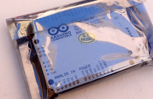
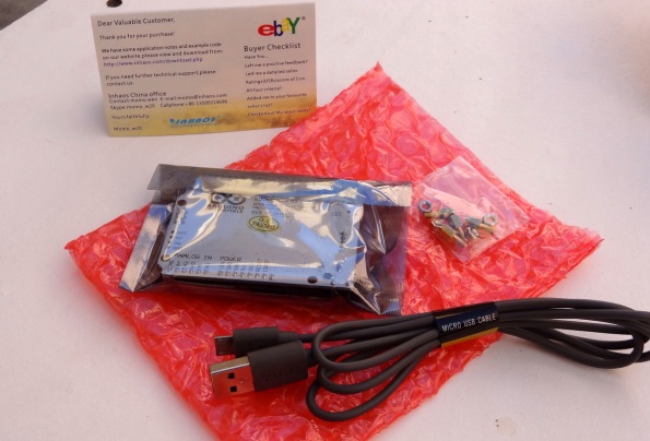
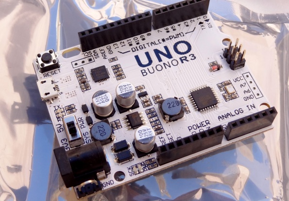
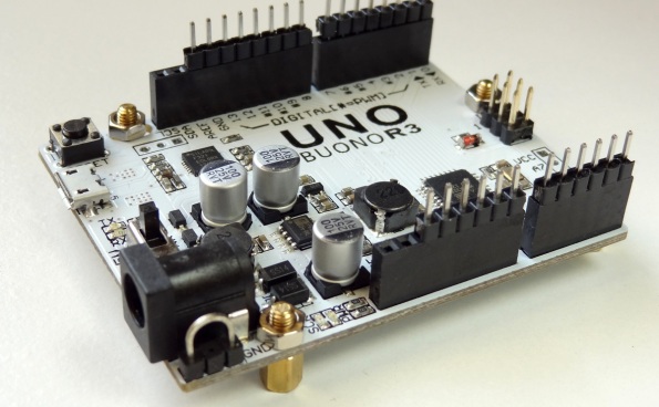
Using my latest favorite Arduino clone (only $10) [link]. The two small boards hanging on the pins are a LCD backlight control and a 5V to 3.3V level converter. As I realize that this audio diy hobby is never ending, I figure doing things the easy way trumps doing things the neat way (like for example using an Arduino shield) so I soldered the wires directly on pins that I plug into the board.
NEW Arduino Compatible
BEST DEAL
For US$10, it is a heck of a deal. [link]
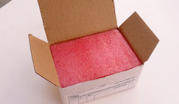
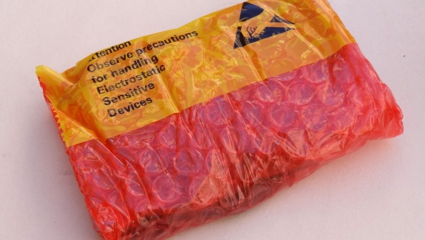
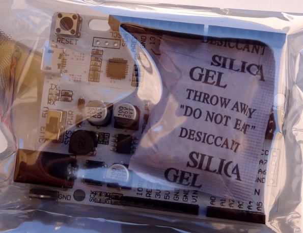
EXCELLENT PACKAGING
Use of excellent padding, anti-static bag and silica desiccant.
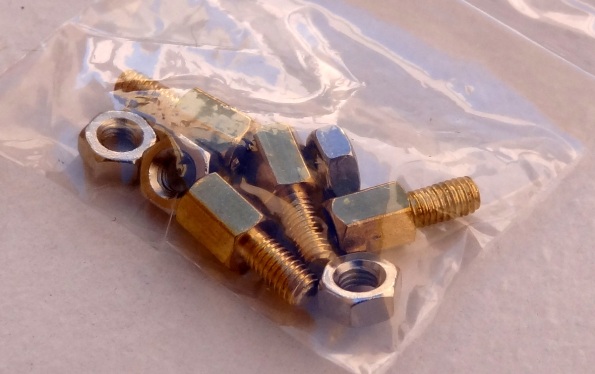
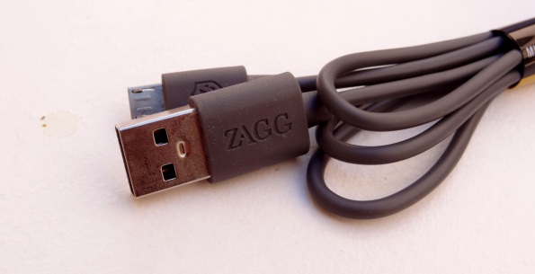
ACCESSORIES
Very nice USB cable and mounting hardware
INNOVATION and IMPROVEMENTS
Features implemented in the BUONO:
- Selectable voltage operation: 3.3V or 5V
- Better location for LEDs and reset switch, especially if you use a shield
- Higher power. Maximum of 1.8A for peripheral devices
- Cleaner AVCC. LC Low pass filter for the AVCC allows the ADC to be more accurate
- Easy access ground terminal to facilitate measurement and trouble shooting
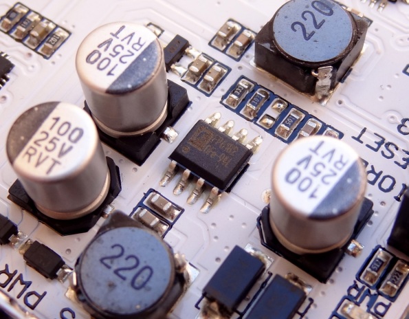
Power is provided by the FP6182 DC-DC converter [link]. It can provide up to 2A of current
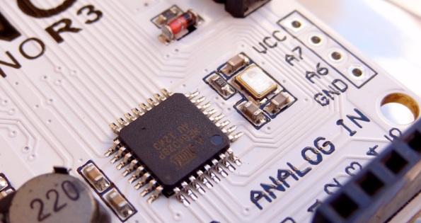
SDM microprocessor and high quality crystal oscillator.
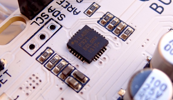
Silicon Labs C8051F321 USB bridge chip [link]. (Make sure you have the latest firmware [link]) for full compatibility with Arduino UNO R3,
I am not sure why use a Silicon Labs parts, except it may be less costly and does not require an external oscillator.
The USB MCUs feature an on-board universal serial bus (USB) 2.0 function controller with an integrated transceiver and on-chip clock recovery. No external resistors, crystal, voltage regulator, EEPROM or other components are required. On-chip resources include a high-speed 8051 CPU with up to 64 kB Flash, UARTs, SMBus, SPI, timers, counters and PWM generators. On-chip analog features include a multi-channel 10-bit ADC, voltage reference, internal oscillator, comparators and a temperature sensor. Available in 28-pin QFN, 32-pin LQFP or 48-pin TQFP packages, these devices provide a single-chip solution for embedded USB applications.
TESTING THE ARDUINO-COMPATIBLE BUONO
The Arduino Buono R3 is an Arduino UNO clone. It is designed to behave exactly as the Arduino UNO R3.
I wanted to make sure it is a fully fully functioning before I test the rest of the system.
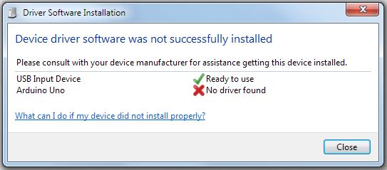
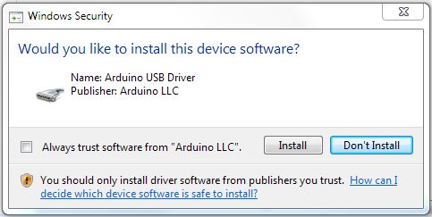
1- Plug the device to a USB port with the included micro-USB cable. Immediately you will see that the OS will recognize the device and attempt to load the Arduino UNO driver. If you do not have the Arduino software installed, the computer will not find the device driver
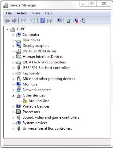
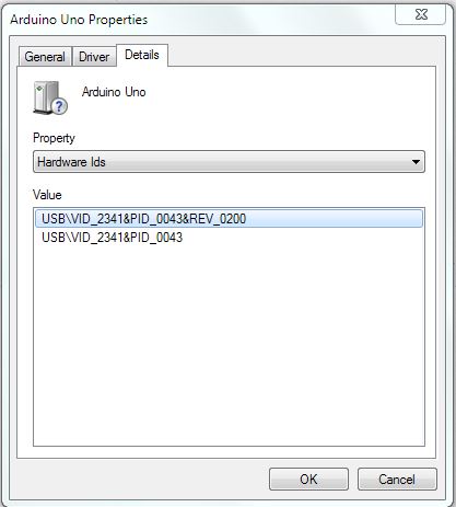
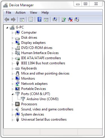
2- The next step is to check the FW version, and ensure it is version 0200 or newer (check on the device manager for “Arduino UNO”). The manufacturer website has the instructions to install the latest firmware [link]
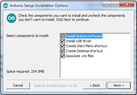
3- Download the Arduino software and install it. It will also install the USB driver.
Confirm that you want to install the Arduino USB Driver.
After installation, the Arduino UNO will be recognized as a periphery device. In this case a serial device in COM3
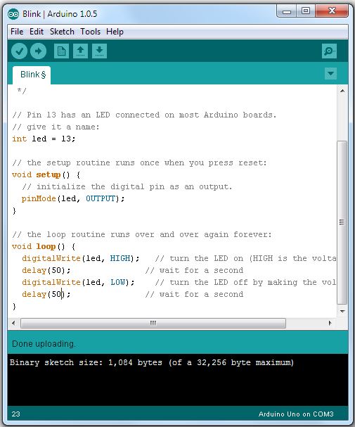
4- I like to test with the “BLINK” sketch. Open the sketch in the Arduino software and upload it to the Arduino. If everything works as expected, the device should be fully operational.
Additional information from the manufacturer: [link], [link]
New Version of Code
FULL SUPPORT FOR “SMART INPUT SWITCHING”
I finally tested the “Smart Input Switching” for the Sabre DAC as proposed here: [link] and implemented in QuangHao’s DAC-END R [link]. I connected the Amanero USB board and also a Toslink SPDIF source to the DAC, and had both sources live at all times.
The DAC-END R connects the Toslink through SPDIF #3 as shown in this diagram (borrowed from here: [link])
Had to fix the code in order to make it work. I discovered a couple of things on how the Sabre32 DAC chip behaves:
- When switching from SDPIF input to Serial input, it is not sufficient to switch the input format. One must also switch the SPDIF MUX to an input that does not have a live SPDIF signal (I switched it to SPDIF#1 which is shared with the I2S connections). If you do not do this step, the status register will report an SPDIF data stream even though you are receiving an I2S stream, and the sample rate calculation will be completely wrong. However, this has no effect on the sound.
- “Auto SPDIF detection” must also be set in the registers when using any of the SPDIF inputs. It is not sufficient to just select the SDPIF input port. If you do not do this step, the DAC will not receive the SPDIF data stream.
In summary:
| Switching | Reg8: Source |
Reg17: Auto SPDIF |
Reg18: MUX |
| SPDIF to I2S/DSD | I2S/DSD | Off | Select SPDIF #1 |
| I2S/DSD to SPDIF | SPDIF | On | Select SPDIF channel |
The code shows the implementation and register settings. “Smart Input Switching” has great appeal because no additional components such as relays or solid state muxes are required resulting straight wire input for any of the sources.
CLEANER CODE FOR DUAL MONO
Recognizing that for the most part changes in register values for one chip in dual mono configuration are the same as for the other chip, I modified the register writing routines to write the same value to both chips even in dual mono. After all the values are written, register 17 is changed for “right channel” and the value is written to the RIGHT chip. This greatly simplifies the programming for dual mono configurations.
Note: not yet tested since I do not have a dual mono configuration.
CODE AVAILABLE IN THE “CODE” TAB
The code is available in the usual place.
NOISE IN I2C: ARDUINO FREEZES
When using the HiFiDuino controller with DAC-END R, I experienced the Arduino controller freezing shortly after power-on. Eventually I traced the problem to the I2C library code in Arduino, which freezes when there is noise in the I2C lines (the functions never return, hanging the micro controller). During experimentation, I tried different things:
- Added smaller pull-up resistors. This improves the I2C waveforms [link]. I used 1.5K pull ups
- Added bypass capacitors to the 5V and 3.3V right at the level shifter board
- At first I forgot to ground the DAC chip reset line. So I grounded the reset line
- Twisted the I2C lines for noise immunity
…but the improvement were very small. The controller would still freeze a few minutes after power on.
It turned out that the noise was caused by the I2S wires crossing the DAC chip as shown in the photo below. The bitclock is twisted with the ground wire, but the data and LRCK lines are just twisted with each other. Another confirmation that it is a good thing to shield the DAC as I previously discovered [link]
Proper wiring is (as usual) required for proper operation.
Even after uncovering the problem, the above enhancements to the I2C lines (pull-up, bypass, etc) are still worthwhile to do to ensure clean I2C signals.
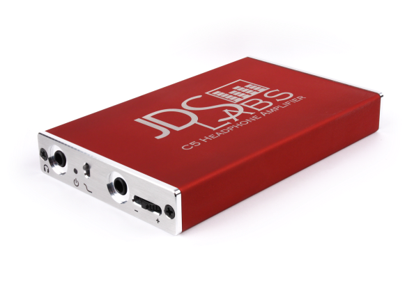
JDS Labs Headphone Amp with Arduino Control
It has digital volume control (DS1882) and the firmware is Arduino based. (Analog volume control with a digitally controlled potentiometer)
And it is open source, Hurray! [link]
The DS1882 is a dual, nonvolatile (NV) digital potentiometer designed to operate in audio systems that accomodate up to ±7V signal levels. The potentiometer settings can be stored in EEPROM so that they are retained when the power is cycled.
Arduino is also used to measure the battery level and indicate a low battery condition.
POWER
There is more: power supplies are based on the TPS7A4700 and TPS713301. The latest ultra-low noise LDOs from TI
Check it out here: [link]
Arduino for Serious Work…
A video interview with Charles Sprinkle of Harman International. He describes the use of Arduino in his day to day work in designing loudspeakers for brands such as JBL.
Using a “Diavolino” [link]
New Version of HifiDuino Code for Sabre32 DAC
Update (11/28/12): I removed version B1.1c because the “optimized” volume control proved to be unreliable. Sometimes coming up at full blast. I reverted to the old volume control in version B1.1d
Sorry about that.
Version B1.1d [link]
2-YEAR ROAD…
I released the first version of the code over two years ago. Along the way, I’ve added features, fixed bugs and optimized the code. It is good to see Hifiduino code used all over the world and I find satisfaction in that 🙂
Luckily (and unlike commercial ventures like Windows :-)), I don’t feel the need to overhaul the code but on the contrary, I think every version, including this one has moved the software to a more mature state in terms of functionality, efficiency and reliability.
Yes, the code can be more “elegant” following a more “professional” style, but I am not a professional coder and getting there takes time and experience. To mitigate that, I’ve extensively commented the code so that anyone can follow how the code works.
Further, the code is not “just code”. As many know, the ESS datasheet is very brief in its information. In certain areas, experimentation was required in order to figure out how to program the registers. Another example is the code for the Apple remote. There is no datasheet you can download; it required experimentation and the charity of a reader who volunteered some critical information unavailable anywhere else.
I feel proud that I’ve accomplished this much, and would like to thank everyone that has been following this blog and using the software. Especial thanks to those that have reported bugs and contributed information. It is no fun just having it for myself 🙂
Enjoy!
WHAT’S NEW
EEPROM writing routine
Thanks to Mr. Corpius, (check out his blog: [link]) I reviewed the writing routine to the EEPROM and changed it to only write if there is a change in the value. This will somewhat help the longevity of the EEPROM. (See below for more information on the EEPROM life)
Sample rate display format
In the last version I changed the sample rate format from an “exact” value (for example “44099”) to a “nominal” value (example, 44.1KHz). But I miss the “exact” value. I’ve added an option to either display the exact sample rate or the nominal sample rate. This option can be selected at anytime just like the other settings and it is saved in EEPROM
Sample rate calculation accuracy
The calculation of the sample rate is based on the formula given in the datasheet on the value of the DPLL number. I had used integer operation in order to speed up and simplified the operation.
In order to verity its accuracy, I have monitored the actual value of the DPLL number for different sample rates, made the calculation “on paper” and compared that with the integer calculation in the code. I found that depending on the sample rate, the integer calculated sample rate is off between 1 Hz to 4 Hz. This is due to the error in the integer factor and to truncation of remainder in the integer operation. I have added this “correction number” to the code and the resultant sample rate is now closer to the real value.
When you see 44100, you can be assured that the actual frequency seen by the DPLL is indeed 44100 Hz (within the frequency accuracy of the on-board Crystek clock which is used as reference)
Input selection choices
In order to support the “smart wiring” configuration for Buffalo III, I’ve added input choices for SPDIF #3, #7 and #8. I’ve also change the selection of I2S, LJ and RJ choices to match the choices available in the Buffalo III SE DAC namely: I2S (32 bit), LJ (32 bit), RJ (32bit, 24 bit, 20 bit and 16 bit).
New options with Buffalo II:
If you are using Buffalo II, then the new SPDIF selections would not do anything ass these inputs are grounded in the BII implementation. The only choice is to use the “SPd” option which connects to input 1.
Prime DPLL
Up to now, the code would “prime” the DPLL when it first locks to a signal. “Priming” of the DPLL consisted in cycling the DPLL through the different bandwidth settings with the hope of reducing the number of unlocks that are experienced with the narrower values of the DPLL bandwidth.
Experienced has shown that unlocks are due to other factors such as warm-up of the oscillators after power-on, external noise and other factors, and thus this function probably served little or no purpose. For this reason, I’ve removed the use of this function from the code.
User Interface tweaks
Moved the oversampling filter indicator one line lower to give more space for sample rate display. With DSD, the sample rate is now 7 digits.
When entering select mode, you will immediately see the settings for input format and sample rate display format. Upon exiting, the input format display will revert to displaying the actual input format (DSD, PCM, SPD or SP<-, SE<-) indicating the type of data stream received or the input format setting if there is no signal. The sample rate format will reset to displaying the actual sample rate.
Volume adjustment routine
(Update 11/28/12). This “enhancement” proved unreliable. I’ve reverted to the “Before” way of adjusting the volume in version 1.1d. I’ve deleted the version where I “improved” the code.
Rewrote the I2C volume adjustment routine by taking advantage of repeated writes to the 8 volume registers without releasing the bus. This only works in Arduino if the registers are in sequential addressed starting from the first address. Functionally, this is the same, but a bit faster.
Before:
Wire.beginTransmission();
Wire.write();
Wire.write();
Wire.endTransmission();
Wire.beginTransmission();
Wire.write();
Wire.write();
Wire.endTransmission();
Wire.beginTransmission();
Wire.write();
Wire.write();
Wire.endTransmission();
// etc...
Improved code:

Wire.beginTransmission();
Wire.write();
Wire.write();
Wire.write();
Wire.write();
// etc...
Wire.endTransmission();

(This "improved" code proved to be unreliable...)
Remote control bug
Fixed a bug that prevented the repeat of keys from the remote. By default, all keys from the remote are treated as non-repeating unless explicitly specified. When you hold down a key in the Apple remote, after the first command byte, the next command byte is a generic “repeat” value. The code recognizes the repeat key only for keys that are specified as “repeat”.
When I changed the control byte from 8 bits to 7 bits, I forgot to change the values to the new values of those keys.
Code and comments clean-up
Minor code clean-up. Also reviewed the comments and clarified where needed.
Support for other Sabre32 based DACs
No code has been changed, but based on compatibility with BIII as indicated in this post [link], this code can be used in other Sabre32-based DACs.
Licensing
I’ve added a Creative Commons License if for no other reason that some people have asked me before they decide to use the code. This is also good practice and lowers the risk of any potential copyright issue.
I’ve chosen the most permissive license available under Creative Commons:
![]() This work is licensed under a Creative Commons Attribution 3.0 Unported License.
This work is licensed under a Creative Commons Attribution 3.0 Unported License.
This license lets others distribute, remix, tweak, and build upon your work, even commercially, as long as they credit you for the original creation. This is the most accommodating of licenses offered. Recommended for maximum dissemination and use of licensed materials.
Keep in mind that in the absence of any explicit licensing, there is an automatic copyright for any work created.
Under the Berne Convention, copyrights for creative works do not have to be asserted or declared, as they are automatically in force at creation: an author need not “register” or “apply for” a copyright in countries adhering to the Berne Convention [link]
Thus if someone wishes to use the code for a project, that person doesn’t know whether in some future I would bring up a copyright claim. With the explicit Creative Commons license, the legal uncertainty is removed.
KILLING THE ARDUINO EEPROM?
The eeprom in Arduino is used to store all the DAC settings that are assigned for a particular input. The default configuration of the code has 6 selectable input configuration, each having its own set of DAC parameters (such as FIR setting, DPLL setting, etc). In total, with this default configuration, there are 49 values that are stored in the EEPROM.
The life of the EEPROM for the ATMEL chip in Arduino is specified at 100,000 writes per cell [link]. Keep in mind that the lifetime is per memory cell, so even if writing 49 values, it counts as one “write cycle” because the 49 values are written into different cells. One experiment showed failure after over one million “write cycle” operations [link].
Operation of code
The current version of the code will write all the parameters every time you exit the select mode. In order to make an input selection or to change any parameter, you enter the select mode. Thus every entry into the select mode constitutes one write cycle.
Lets say you are are an audiophile and also enjoy tweaking your system speinding a lot of time listening to sound artifacts.
Lets say on average, during your listening and tweaking sessions, you make say 100 difference parameter adjustments or input selections. For example you may want to test DPLL settings or do an A-B comparison between two sources. Each of these count as one write cycle to the eeprom
In such situation the EEPROM will “last” 100,000/100=1000 days. If you do this every other day, then effectively you have a minimum life span of 5.5 years. Even if you do this every day, the minimum life is 2.7 years based on the datasheet value. If we use experimental data, the life span can be as long as 10x the specified value.
Hifiduino Code and Buffalo III DAC
HOW COMPATIBLE IS THE HIFIDUINO CODE WITH THE BUFFALO III DAC?
People have successfully used the HIFIDUINO code with the Buffalo III DAC, and I have generally said that “it should work”, but I had never tried to figure out whether there are any incompatibilities, inconsistencies or bugs when used with the Buffalo III DAC, primarily because I didn’t one have to test with.
I’ve now decided to do some theoretical study on how compatible is the HIFIDUINO code with at least the “commonly” (or default) STEREO or MONO configured Buffalo III DAC. I am doing this to satisfy my own curiosity and to give confidence and peace of mind to those using the code for the Buffalo III DAC, which I believe is now more widely used than the Buffalo II DAC. As audiophiles, we care as much about sound as the “perfection” of the audio chain 🙂
BUFFALO III “DEFAULT” CONFIGURATION
Based on the BIII integration guide, the default STEREO configuration (jumpers, connections and dip-switch selection) for I2S and DSD is as such:
For reference, here is the configuration for Buffalo II on which I test my code. We will compare the Buffalo III input configuration with the input configuration of the Buffalo II DAC. If we find that the two are equivalent, then as far as the code is concerned, there is no incompatibilities to worry about. The code can’t tell whether it is controller a Buffalo II or Buffalo III DAC as they are based on the same chip and the only difference is how you configure the inputs.
ANALYSIS AND OBSERVATIONS
The first thing we observe is that the Bufalo III DAC default DSD configuration is “covered” by the BII input configuration. In other words, the wiring for the Bufalo III DAC for DSD is a subset of the wiring for the Buffalo II DAC. Both configurations require that you remap the inputs
How about for the I2S configuration?
Notice that the default Bufalo III DAC configuration for I2S does not require that the inputs be remapped. But for the DSD configuration, input remapping is required. Wouldn’t it be nice if for both configurations we can use the same “input remapped” setting? This would eliminate the need to be changing the input mapping configuration every time you switch between a PCM source to a DSD source
Thus, if we remap the inputs (which is just a software register setting), we can remove one of the jumpers and still feed all the internal DACs like this:
We notice that there is no use for Data 3; but we also know that there is no harm having a live signal on that pin (because the same thing happens in the BII without adverse effect) and thus, there should be no harm even if you leave the 3rd jumper in place.
With this equivalent configuration for the Buffalo III DAC for I2S, we also realize that it is covered by the Buffalo II input configuration.
FULLY COMPATIBLE
Because in the default configuration, the Buffalo III DAC input wiring is equivalent to the wiring of Buffalo II DAC, the HIFIDUINO code is fully compatible with the default STEREO configuration of the Buffalo III DAC, whether in its I2S mode or in its DSD mode.
By extension, therefor, the code is also fully compatible for a DUAL MONO BUFFALO III configuration.
HOW ABOUT 8-CHANNEL MODE?
The first thing to do in order to support 8-channel is to undo the input remapping. This can be done in register 14:
Register 14
|0|x|x|x|x|x|x|x| Source of DAC8 is DAC8 (D)
|1|x|x|x|x|x|x|x| Source of DAC8 is DAC6 (Use this to match BII input wiring)
|x|0|x|x|x|x|x|x| Source of DAC7 is DAC7 (D)
|x|1|x|x|x|x|x|x| Source of DAC7 is DAC5 (Use this to match BII input wiring)
|x|x|0|x|x|x|x|x| Source of DAC4 is DAC4 (D)
|x|x|1|x|x|x|x|x| Source of DAC4 is DAC2 (Use this to match BII input wiring)
|x|x|x|0|x|x|x|x| Source of DAC3 is DAC3 (D)
|x|x|x|1|x|x|x|x| Source of DAC3 is DAC1 (Use this to match BII input wiring)
Quantizer bit depth also affects input remapping as follows:
As you increase the quantizer bit size, the DAC internally turns off the digital sections for half of the DACs and replicates the output to all the analog sections of the DACs. Further increase of the quantizer bit size further turns off the digital sections for half of the remainder DACs resulting in using only one quarter of the digital sections of the internal DACs. Thus, whereas all the analog sections are always fully utilized, the number of channels available in the DAC depends on the quantizer setting as follows:
| Setting |
Quantizer | Input Channels Used |
Output |
| 1 | 6-bit | 8 (All) | 8×1 – 8-Channle |
| 2 | 7-bit | 8 (All) | 8×1 – 8-Channel |
| 3 | 8-bi | 4 (#1,#2,#5,#6) | 4×2 – 4-Channel |
| 4 | 9-bit | 2 (#1 and #2) | 2×4 -Stereo |
This means that the only allowable quantizer setting for 8-channel is 6-bit and 7-bit. The current code supports all settings so in order to configure for 8-channle, you just make the correct selection in the user interface.
Therefor, the code can be made fully compatible with 8-channel by just making a small change in the code. When i get a chance I’ll incorporate this into the code and make it an option.
Buffalo III “Smart” Stereo Input Configuration
Here is a “smart” input configuration for the Buffalo III DAC, where you can use an interface like the Amanero USB that can pass both I2S and DSD and also connect 3 other SDPIF sources without any external switching device. This configuration leverages the Serial format auto-detect capability of the Sabre32 DAC and its built-in SPDIF MUX. It also requires an external controller such as HIFIDUINO.
In essence, it replicates the input configuration of the Buffalo II DAC and frees up 3 input ports for SPDIF.
BUFFALO II (FACTORY CONFIGURED) INPUT
Notice that in the Buffalo II DAC, Data 3, Data 7 and Data 8 are connected to GND. In contrast, all the input lines are configurable in the Buffalo III DAC. The idea here is to replicate the “D1” and the “D2” connections of the Buffalo II DAC and have Data 3, Data 7 and Data 8 available for SPDIF input.
Also notice that the input to the 8 internal DACs are remapped so that only inputs to 4 DACs are required. This remapping is accomplished through the appropriate register (register 14). The integration manual for BIII also specifies input remapping for the “default” stereo configuration.
With this input configuration the DAC automatically switches between a PCM (I2S) stream and a DSD stream. This behavior has been tested with the Amanero board, and it should work with other boards such as the EXA device. [link]
BUFFALO III INPUTS
Here is the input pins for the BIII DAC board (top and bottom).
According to the Buffalo III Integration guide by Leon van Bommel (54 pages worth of excellent documentation). The jumper settings is as such:
The table implies separate input configuration for PCM and DSD. The rest of the guide also instructs the installation and removal of jumpers and dip switch settings depending on the input format (SPDIF, DSD or PCM).
SMART WIRING FOR BIII DAC
Without going further, let me say that this only works for stereo configuration.
By comparing the jumper setting table for BIII with the BII wiring diagram above, we notice that in order to replicate the BII input wiring on the BIII DAC we can do the following:
Use JDSD1 and JDSD2 and then find a way to wire D4 to D2 or to D6. This can be done by using JPCM2 and JPCM3 (and we loose the use of D3). This can also be done by installing an external jumper from D4 to D6 or from D4 to D2. D3, D7 and D8 are made available for SPDIF inputs.
The complete wiring would look like this:
USING HIFIDUINO CONTROLLER
Combining the above configuration with an external controller such as HIFIDUINO, and the appropriate interface (for example Amanero USB) you will be able to enjoy the convenience of switching between PCM, DSD and 3 external SPDIF sources without making any changes in the jumpers or dip switches of the board.
The current version of the code supports does (not yet) have support for actuating the built in SPDIF MUX, but a simple change is described by Mr. Corpius here: [link]
NOTE
I do not have a BIII, but I have done testing on my BII where I had both SPDIF and I2S signals connected and live at the same time. I was able to switch from I2S to SPDIF by just switching the signal on one pin (D1). You can read more in the Sabre32 tab. Look for “LEVERAGING INTERNAL SOURCE SELECTION”. However, Russ (from TPA) just commented on this post, and expects this configuration to work. You can read his comments in the comments section.
UPDATE (11/17/12)
The DSD channels are swapped with respect to the PCM channels [link] and both channel arrangements are “standard”. This means that this “automatic” switching works, but the DSD channels (or PCM channels) need to be swapped. The wiring can obviously be swapped with a relay, but then it is not “automatic” anymore, and you now have a relay in the signal path.
The solution is to swap the DSD channels in the foobar player. I’ve documented the procedure here: [link]
UPDATE (11/20/12)
Bunpei recommended this wiring configuration a while back [link]
New Version of Code: v 1.1a
SAMPLE RATE DISPLAY COMPATIBLE WITH DSD, PCM and SPDIF
Finished a small update to improve the display of input format and sample rate. Also, the Apple remote code now supports all remotes without code change. This is how it looks like when displaying different input formats and sample rates.
The sample rate and input mode (PCM, DSD or SPDIF) are reported by the Sabre32 DAC in the status register, so what you see is always the truth. As you evaluate different interfaces you will immediately know if what you expect is what you are getting, such as for example, whether there is sample rate conversion and whether DSD is converted to PCM.
I decided to show the nominal sample rate rather than the exact sample rate as calculated by the DPLL. The actual sample frequency varies from adapter to adapter but it is typically within a few hertz. For example 44 KHz will measure at 44099 Hz or 44101 Hz.
The code continues to calculate the exact value of the sample rate and is available in case anyone wishes to make use if it. For example, the older models of the Musiland interfaces had a “fast” and “exact” mode in generating the sample rate. In “fast” mode, the sample rate deviated from the standard value “quite a bit” (but still within the specified tolerances) so it was interesting to see the actual sample rate, which in this case was 44121 Hz for the 44100 Hz standard.
I2S INPUT FORMAT SELECTION
In addition, I’ve added selection of I2S format: 32 bit (“I32″), 24 bit (I24”), etc; left justified and right justified formats as specified in the data sheet. These settings are only shown when you enter “select” mode as shown below.
APPLE REMOTE CODE IMPROVEMENT
Thanks to a tip by a reader, the command byte in the Apple remote protocol is only 7-bit rather than the full 8-bit. By making this adjustment (only one line of code required), the code is now compatible with ALL remote controls manufactured by Apple, including the white plastic model. For more information, check the Apple Remote tab: [link]
CODE CONFIGURATION
Same code configuration as before:
In order to support your device and configuration look for this section in the code and make the changes as instructed in the code:
/******************* Code Customization Section *********************/

/* First: Choose the clock frequency you have and comment the other */

#define USE80MHZ
//#define USE100MHZ

/* Second: Choose your configuration

   | CONFIGURATION       | #define DUALMONO | #define TPAPHASE |
   |---------------------|------------------|------------------|
   | Dual mono in-phase  | un-comment       | comment          |
   | Dual mono TPA phase | un-comment       | un-comment       |
   | Stereo              | comment          | comment          |
   |---------------------|------------------|------------------|    */

#define DUALMONO
#define TPAPHASE

/* Optionally choose the number of inputs. 6 is the max without
   modifying the code. You could lower the number of input choices
   here                                                             */

#define ICHO 6

/* Optionally change the name of the inputs. Keep 6 characters
   Use blanks if necessary                                          */

char no0[] = "PC-BST";
char no1[] = "APPLtv";
char no2[] = "SPDIF1";
char no3[] = "DENON ";
char no4[] = "SACD-1";
char no5[] = "AMNERO";

/* Make sure you use the correct chip address for each board

   for stereo Buffalo: use address 0x90
   for dual mono: Use address 0x90 for mono left Buffalo
                  Use address 0x92 for mono right Buffalo           */

/********************************************************************/
The code above is configured as 80 MHz, DUALMONO TPAPHASE
WHERE IS THE CODE?
You can download the latest code from the CODE tab: [link]






Latest Comments