Firmware v 0.99
The long awaited firmware update for the Soekris DAC is out.
| Parameter |
Firmware 0.9 |
Firmware 0.99 [link] [link] |
| Digital Filters FIR1 Coefficient Size and Format | FIR1: 32 bit, 2.30 format
FIR2: 32 bit, 2.30 format |
FIR1: 32 bit, 1.31 format (one bit of increased precision).
Should be good down to around -150 db. Increased precision improves frequency response (pass band ripple and stop band attenuation) [link] -One extra bit of precision adds 6 db improvement. FIR2 format remains the same. |
| Digital Filters FIR1 Number of Coefficients | 1016 max coefficients | Twice the number of coefficients resulting in 2032 max coefficients. Basically anything possible with software resampler (such as SOX) will be possible in the DAC. |
| Digital Filters FIR1 and FIR2 Filter selection | A single filter per supported sample rate. Changing filters requires uploading the new filters through the serial interface. To switch to the new filters a power cycle, input switch or sample rate change is required. | 4 banks or FIR1 and corresponding FIR2 filters per supported sample rate can be individually selected. (FIR1 filters specified as type 4-7 corresponding to banks 1-4 and FIR2 filters specified as type 8-11 corresponding to banks 1-4). NOTE: For simplicity in creating filters: if a specific FIR1/FIR2 filters are only specified once for bank 1 (FIR1 type 4 and FIR2 type 8), then they are used for the other banks e.g.: [link]
The factory filters are: Linear, Mixed, Minimum and Soft. As before, new filters can be uploaded replacing the factory filters. Example filter configuration: [link] A filter bank can be selected by selecting the FIR1 type (4-7) or name given to the filter. The corresponding FIR2 filter in the bank is automatically selected. A power cycle, input switch or sample rate change is first required when uploading new set of filters. |
| De-emphasis Filter | “Original” | “Improved”. Note: de-emphasis filters are always loaded, but only enabled when emphasis bit is set in spdif datastream [link]. If a CD is ripped, then the emphasis bit is lost. It is up to the ripping s/w to detect the emphasis bit and apply de-emphasis when ripping. Apparently only iTunes can do this automatically: [link], [link] |
| Digital volume control | -99 dB to 0 dB | -80 dB to 10 dB with zero crossing detect (to eliminate glitches during volume level transitions). Also fixed the polarity inversion bug [link], [link] |
| Locking to incoming data bitclock and wordclock | > 1 sec (up to 2-3 sec). This happens when the incoming bitclock and/or wordclock is interrupted or changes frequency when changing tracks | < 0.2 sec, near instantaneous. Locking pops [link] initially present in the first release of the new firmware have also been fixed (same version number) |
| Interrupt-driven Serial Port | No | Yes. This prevents loosing characters at high speed (prevents the DAC from loosing characters when a computer or microprocessor sends commands to the DAC at high speed) |
| Input selection | Auto, SPDIF 1, SPDIF 2, I2S (although it does not quite work) | Same: Auto, SPDIF 1, SPDIF 2, I2S (bugs fixed) |
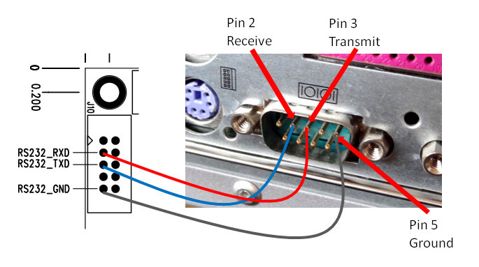
| Isolated 3.3V Serial ports | Not enabled | Enabled. Can be used to interface to uP like Arduino or Raspberry Pi for external s/w control without having to use a serial to RS232 converter device [link] |
| Output Mode | Stereo only | Normal Stereo, Inverted Stereo, Mono Left, Mono Right. In Mono, the raw output is also in balanced mode.
For multiple boards, the plan is “to daisy chain the serial ports, the echo of all commands should make it possible. Then use volume pot and input selector on the first one in the chain… Paralleling the I2S and Toslink inputs are easy, SPDIF might require buffering…” However, perhaps a better solution is to use separate serial ports to control each board (if for only setting one board MONO Left and the other MONO Right). An Arduino Mega or DUE has multiple serial ports. |
| Activate newly uploaded firmware or filters | Power cycle | In uManager, after download type “update” and then type “exit” to exit the uManager (and return to “play” mode). “update” should only be used to update the firmware because it erases and rewrites the uC internal flash which is a high risk process. [link]. I believe power cycle will do the same thing (but didn’t try) |
NOTES
- Input rate of 352.8K or 384K will result in FIR1 being bypassed [link]
- uManager settings (filter, volume, etc) are stored in flash and survive power cycling. This is used to setup power-on default settings.
- In uManger, “set filter =…” should be “set filters = …”
Updates to Firmware:
1.05 filters are the same as 0.99 filters, only added support for DSD rates which require their own filter definitions. The filter files are interchangeable, but for DSD to work you of course need the DSD filters….
1.05 had bugs which in certain circumstances could cause the dam1021 uC to lock up, that should be fixed in 1.06. Any other versions was test versions and should be gone by now…. [link]
COMMAND INTERFACE
| Area | Play-mode Command interface |
Setting Command interface (uManager) |
Comments |
| Best Usage | Microprocessor Control | Setting power-on defaults, interactive control | Settings with uManager are saved to flash and survive power cycle. Note the use of capital letters when using “play-mode” interface |
| Input Selection | Ix | set input = x | x=0: I2S Input
x=1: SPDIF 1 (typically coax) x=2: SPDIF 2 (typically toslink) x=3: auto. It locks to the first detected active input in the order I0, I1, I2 |
| Volume Control | Vxx | set volume = xx | Sets volume to xx level in dB. xx = -80 to +10 |
| V-99 | set volume = -99 | Enables potentiometer volume control. NOTE: If set to other than -99 and the potentiometer is connected, the DAC may be MUTED (having no output whatsoever and unresponsive to the volume pot) -at least this was the behavior in the older firmware. | |
| Show Filters | N/A | filters [all] | Show current selected filter (“filters”). Show all possible filters (“filters all”) |
| Switching filter bank | Fx | set filters = “name” | Select filter bank with immediate effect. Both FIR1 and FIR2 filters in the bank are selected. [link].
x=4-7 representing filter banks 1, 2, 3 and 4. “name” is “linear”, “mixed”, “minimum”, and “soft” are are mapped to filter banks 1, 2, 3 and 4 regardless of what type of filters you have in those banks. [link]. Note: although “set filters” can be used to select filters, is meant for setting the default filter. At power up, the DAC is always at the default filter |
| Other Commnads | N/A | See –> | Enter/Exit uManager: “+++” to enter; “exit” to exit
Set serial communication speed: “conspeed=xxx“. I think only use if having problems with the highest speed: 115200 Set mono/stereo: “mode=x“. x=”normal”, “invert”, “bal-right”, “bal-left”: Normal STEREO, Inverted STEREO, MONO Left, MONO Right. In MONO, the raw output is also in balanced mode. Update firmware (not to be used when uploading new filters): “update“. NOTE: “update” should only be used to update the firmware because it erases and rewrites the uC internal flash which is a high risk process. |
UPLOADING THE NEW FIRMWARE
Summary of steps:
Connect DAC RS232 port to RS232 port in PC
- Start the terminal application and configure the serial port parameters
- Enter DAC uManager by typing “+++”
- Type “download” and use the terminal application Xmodem transfer facility to upload file
- Type “update”, then acknowledge update with “y” (yes) – Caution: Don’t use “udpate” when just uploading filters
- Type “exit”
Connect the RS232 Interface to a PC
Since this is the first time the isolated serial ports have been enabled, the existing firmware in the DAC can only communicate via the RS232 ports.
Connect the RS232 pins to the PC serial port as follows. This is basically a null-modem connection without h/w flow control. You may want to check this informative site on serial communications including RS232 [link]
Launch the Terminal Application
I use “Tera Term” [link]. The latest version is 4.87 and it works well with Windows 10. A mini tutorial can be found here [link].
Select “Serial” connection upon startup of the application. Configure the serial communication parameters with the following settings by selecting “Serial port” in the “Setup” menu:
- Baud rate: 115,200 (This is pretty fast. Use a good, short cable)
- Data bits: 8
- Stop bits: 1
- Parity: none
- Flow control: none

Invoking “uManager”
- Type “+++”
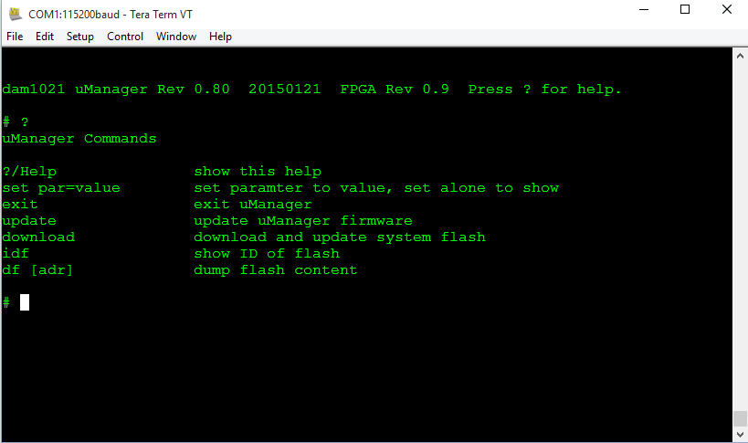
Wait for the DAC to respond (~1 sec). You will see the following message:

Uploading the new firmware
- Type “download” in the terminal window.
uManager will respond with “Start sending file using XMODEM/CRC protocol” and wait for you to start the xmodem transfer.
- In the terminal application “File” pull down menu select “Transfer” -> “Xmodem” -> “Send” from the File menu. Select the file and click “Open”.

Transfer will start immediately:

- Type “update” and then “y” to the prompt “uManager Firmware Update, are you sure?”
- CAUTION: Some users have reported that “update” when just updating filters have bricked the DAC. This is because “The update command should only be used when loading new firmware, it erases and rewrites the uC internal flash which is a high risk process, and if something goes wrong it would require hardware to fix it” [link]

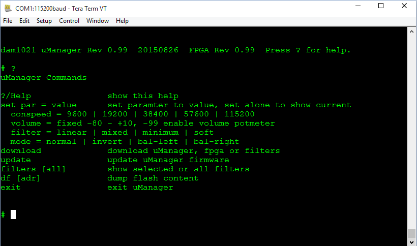
Comparison between uManager 0.8 and 0.99:
RELOADING FIRMWARE IN A BRICKED DAC
Our friend Paul has details on reloading the firmware without uManager (in case you crash/corrupt the firmware and can’t get uManager to work) [link], [link]
The firmware resides on the onboard microprocessor which is is the STM32F030 uC [link].
The pin out of the microprocessor is the following (from datasheet [link])
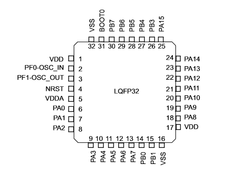
Programming is through the “SWD” pins (from application note AN4325 [link]):

PA13 and PA14 are pins 23 and 24 (lower left corner of the chip)

If you follow the traces, you can see where they are connected in J4:
Requirements:
- Get a hold of a ST-LINK/V2. [link] This is a programmer for STM32 (the microprocessor in the DAC board)
- Download ST-LINK utility [link] and user’s manual
- Email Soren and ask for a copy of the uManger firmware (also available from Paul’s website -the link above)
Connecting programmer to DAC board
The Pin definition of the ST-LINK is as follows (from user guide [link]):
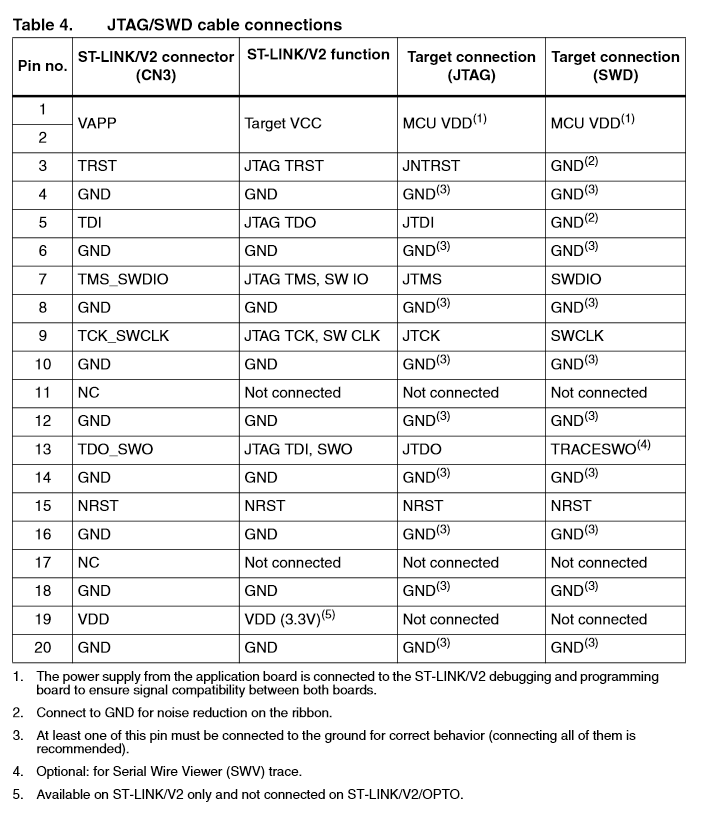
Since the target connection is SWD, we look at the last column and determine that only 5 pins need to be connected:
- Pin 1 or 2: MCU VDD (the VDD of the microprocessor – requires that the DAC board be powered on -also see Note 1 in the table above)
- Pin 20 (0r any GND): GND
- Pin 7: SWDIO
- Pin 9: SWCLK
- NRST (Reset) -This is pin 4 of the microprocessor, not sure if connected to J4

Flashing the firmware
- Select “Erase Chip” to erase the flash in the microprocessor to ensure clean flashing
- Select “Program” or “Program and Verify” and select the uManger bin file (Section 3.5 of the manual)


Hi mate, I really would appreciate some help.
I am going round in circles trying to come up with some code to make an I2C volume control with rotary encoder for the PCM5x DACs.
I’ve been repurposing your older buffalo example code as per the TI datasheet addresses, my scope is seeing data come out of the SDA and SCL lines when I move the encoder, but not working it seems like the DAC isn’t understanding it.
The DAC plays sound okay but I can’t make the volume control work.
I’d be happy even to pay you a small fee to make me some arduino code for controlling this DAC over I2s!
Please let me know 🙂
Test whether you are writing the correct values to the correct register. Write a simple program writing a value into the volume register and then see if the volume changes.
I managed to fix it thanks. were a few probs!
I managed to fix it thanks. were a few probs!
A couple of things….
– “set filter” in uManager is used to configure the default start up filter. It’s not a means of switching filters. The current wording doesn’t make this clear.
– 0.90 firmware does not require power cycle to load new filters. Filters will load on either input or sample rate change.
– I’ve updated the wiring suggestion for hooking up the STM Link programmer. If you don’t have any luck with the setup above, the revised version on my blog should be more reliable and as a bonus allows the board to powered from the adapter.
cheers
Paul
Hello Paul,
Thanks for your input. I’ll update the tables. Regarding the Link programmer, haven’t had the need (and don’t want to try it if I don’t have to :-))
Hello,
I’m very interested in Soekris and now the new V2 version is available on the shop, but the prices are increased.
So I’d like to buy a new board but my wallet suggest me to buy a second hand first version and tweak to save some money.
In your opinion which is the best solution, there are some unknown modifications on the V2 or only what is reported in your forum?
Thanks a lot for your help and your documentation work
Guglielmo
Italy
i see the v1.05 firmware
would u help me to know the different between 0.99 and 1.05
Supports DSD64 DSD128 DSD256.
Faster switches between different frequencies or DSD.
It´s the first perfect version, without noise changes.
thanks a lot
Is there a way to take the I2S directly from the Raspberry Pi and connect it to the I2S input on the dam1021? In terms of performance would this be better then using a USB or SPDIF solution or is it not worth the effort?
Pot Jobs
cialis generique france