Archive
Soekris dam 1021 R-2R DAC ILLUSTRATED GUIDE
(03/24/15) Updated the filter table.
I am consolidating all the user-level information in this post that is spread through several other posts. Where needed, I will clarify and include the latest available information.
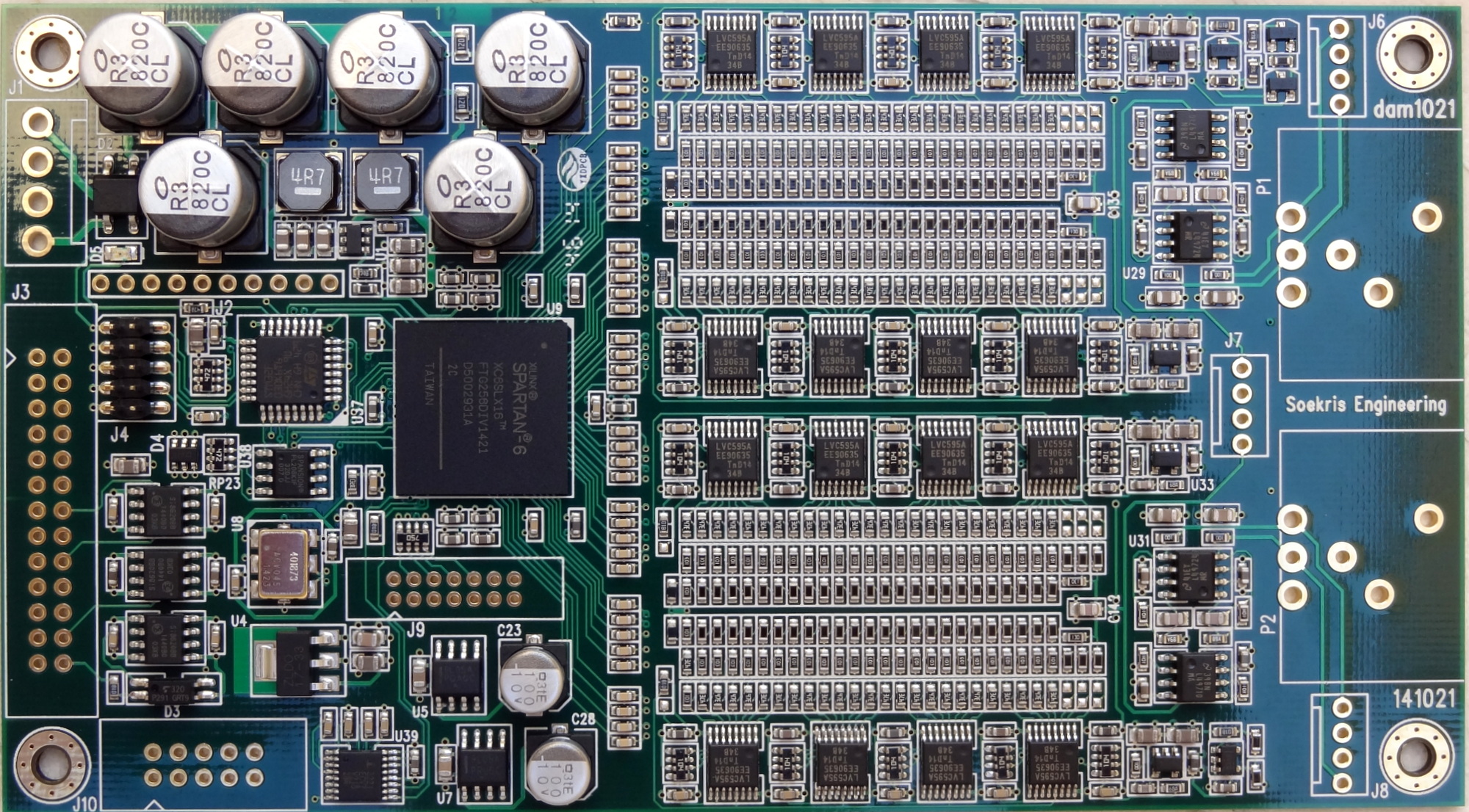
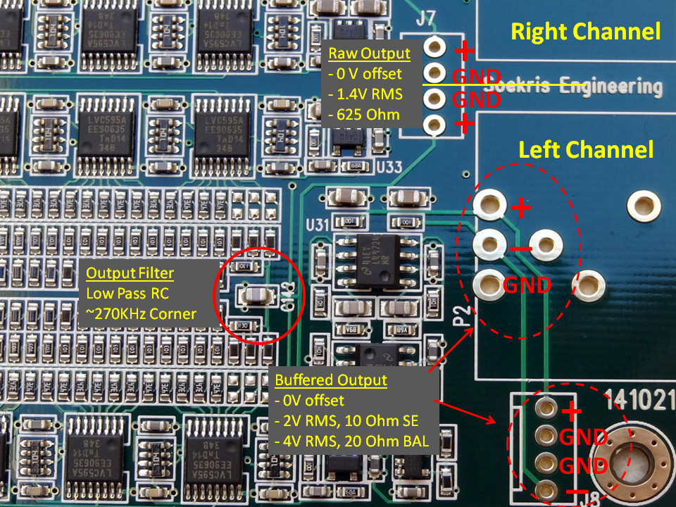
GENERAL LAYOUT
Ref: [1527]
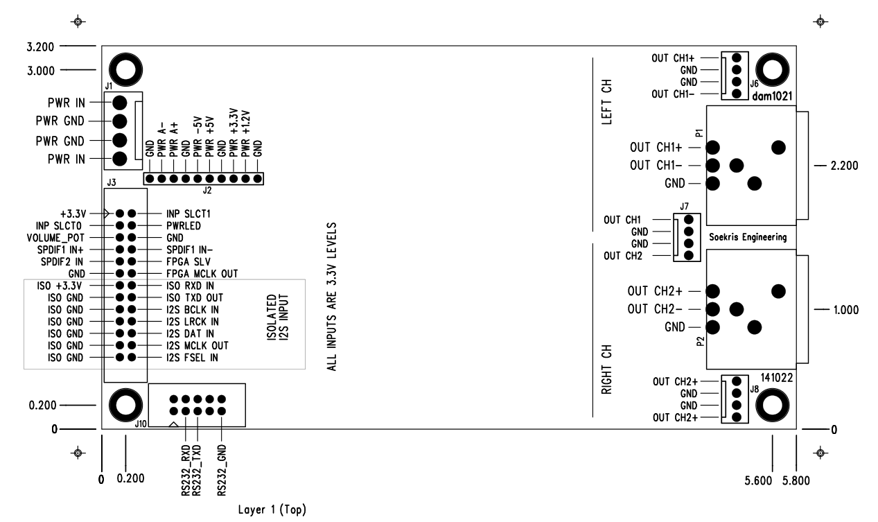
Note: in the diagram above the labels for “RIGHT CH” and “LEFT CH” are swapped. This was noted in the forums [1147] and I also checked it with a R/L test track.
The correct channel assignment (when viewed from the output side) is:
- Right Channel is on the right hand side
- Left Channel on the left hand side

NOTE: it could be possible to swap channels in software, but not possible with the current version of the firmware. Channel assignment is required for mono operation.
Update: firmware 0.99 [link] allows you to configure the DAC as MONO Left or MONO Right, but you still cannot swap the channels.
AUDIO INPUT CONNECTIONS
The dam 1021 supports the following input connections:
- Two SPDIF inputs.
- One Isolated I2S
SPDIF Inputs
You may use one for Toslink and one for transformer isolated Coax as follows [1108]
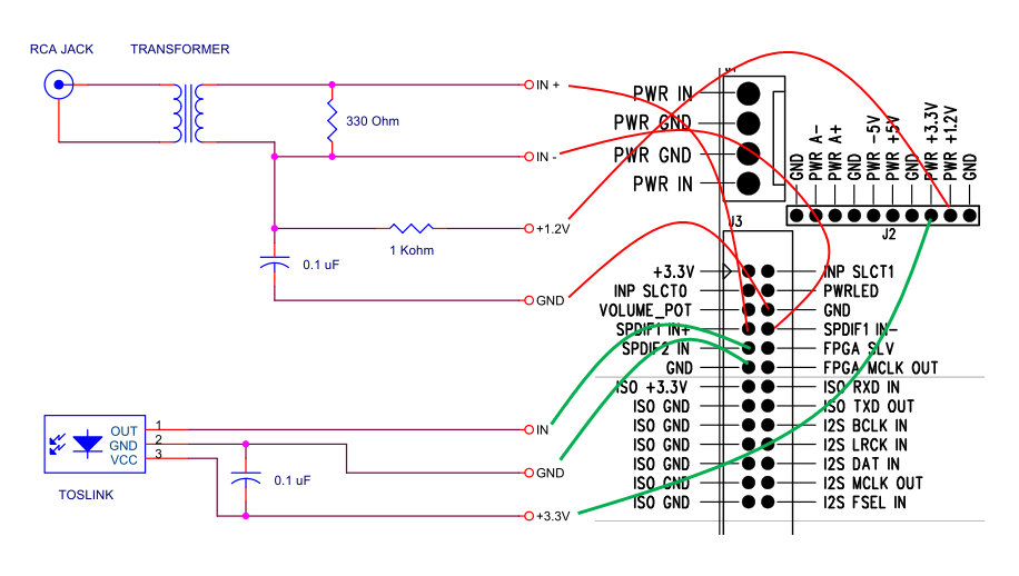
Notes:
1.2v and 3.3v power can be taken off the DAC board as indicated in the diagram.
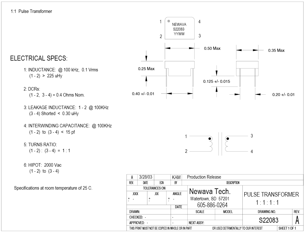
The isolation pulse transformer for the COAX input is a 1:1 type. The Newava Technology Inc S22083 is a favorite [link]. You may find more recommendations in the diyaudio implementation thread [link]
A toslink receiver can be wired as shown in the diagram. The Toshiba TORX147 [link] is a favorite. Seems Toslink receivers are hard to find in the component stores. eBay seems a good source [link]
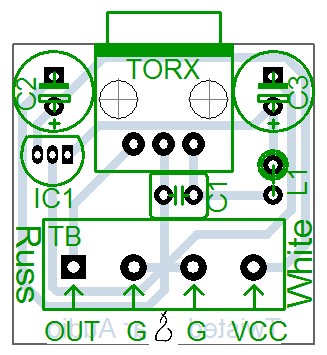
A nice Toslink module is the one from Twisted Pear Audio [link]. (It is the one I own). This one has an on-board 3.3V regulator (IC1 in the diagram below) and is to be powered by 5-12V DC. This one has the Toshiba TORX142 module (25Mb) with supports up 192KHz sample rate (data sheet: torx142l), but Toshiba stopped making them. The current one that is on sale at the TwistedPear Audio store is specified to support up to 96KHz and uses the popular and current Toshiba TORX147.
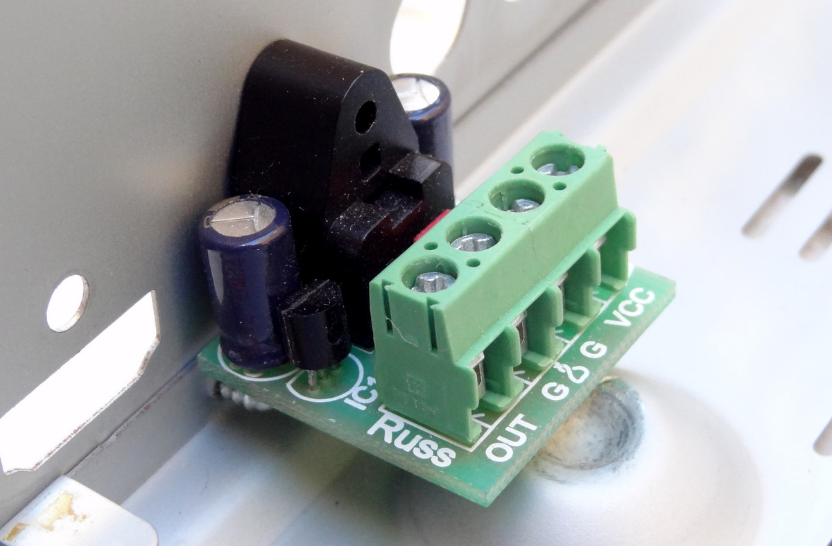
DIYINHK Also has a very inexpensive ($4.00) Toslink receiver: [link]

The difference with the one from TPA is the lack of a local voltage regulator, so you need to provide 3.3V power (which is readily available from the DAC board)
I2S Input (Isolated)
The dam 1021 DAC implements a FIFO reclocker and therefore it does not need master clock input. It works similarly to many modern DACs where an internal PLL or equivalent circuitry locks to the bitclock and generates its own master clock.
The I2S input lines are also noise-isolated with Silicon Labs digital isolators [link]. This means that power needs to be provided to the isolator chips.
Thus the following connections are needed
- Connect I2S source BCLK to DAC I2S BCLK IN Pin
- Connect I2S source LRCK to DAC I2S LRCK IN Pin
- Connect I2S Data to DAC I2S DAT IN Pin
- Provide source 3.3V to ISO +3.3V Pin
- AND connect I2S GND to ISO GND
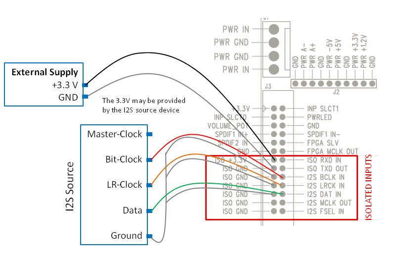
You may also also tap into a 3.3v line in the I2S source if an external supply is not available.
Here is an example using diyinhk USB to I2S adaptor:
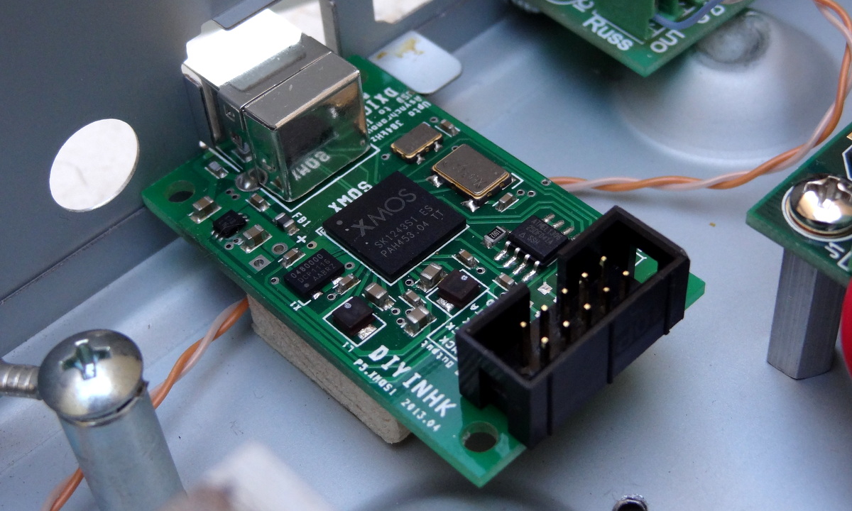

The I2S wires (the multicolored ones)

5V for the ISOLATED INPUTS
According to the data sheet of the the Silicon Labs digital isolators on the board [link], the supply voltage can be 3.3V or 5V. With 5V you can use I2S inputs that are 5V. I have been using 5V supply and works well with 3.3V input signals.
Note that the isolator works by having separate power supplies on each side: the clean side (which is the DAC) and the “dirty” side (which is the I2S source). In order to provide complete digital isolation – meaning “isolated power and ground”, the two supplies must be completely separate. More here [link].
The power supply of the clean side is provided by the DAC board and cannot be externally accessed. The power supply for the “dirty” side is (and must be) provided externally.

Input Selection
The DAC supports automatic or manual input selection as follows:
| Input | INPSLCT0 Pin (J3) |
INPSLCT1 Pin (J3) |
Description |
| Auto Selection | Open | Open | DAC will search the 3 inputs for a valid signal and lock when a valid signal is found |
| I2S | GND | GND | Note that even when not used the USB-I2S interface might output a clock that the dam1021 lock on to…. |
| SPDIF 1 | Open | GND | This input is a sensitive LVDS Receiver -used for Coax [1076] |
| SPDIF 2 | GND | Open | This input is a standard 3.3V digital level -used for Toslink |
I recommend you try Auto Selection first (there is nothing to do). It works very well. Then if you have several sources and more than one active at any time, then implement some circuit (or use an Arduino) to select the desired input.
Signal LOCK indicator
- Steady on: signal lock
- Blinking: no signal or no lock

AUDIO OUTPUT CONNECTIONS
The dam1021 DAC provides the following outputs
- Stereo single-ended RAW outputs
- Stereo balanced buffered outputs which can also be used single-ended
- Both outputs are active and can be used concurrently
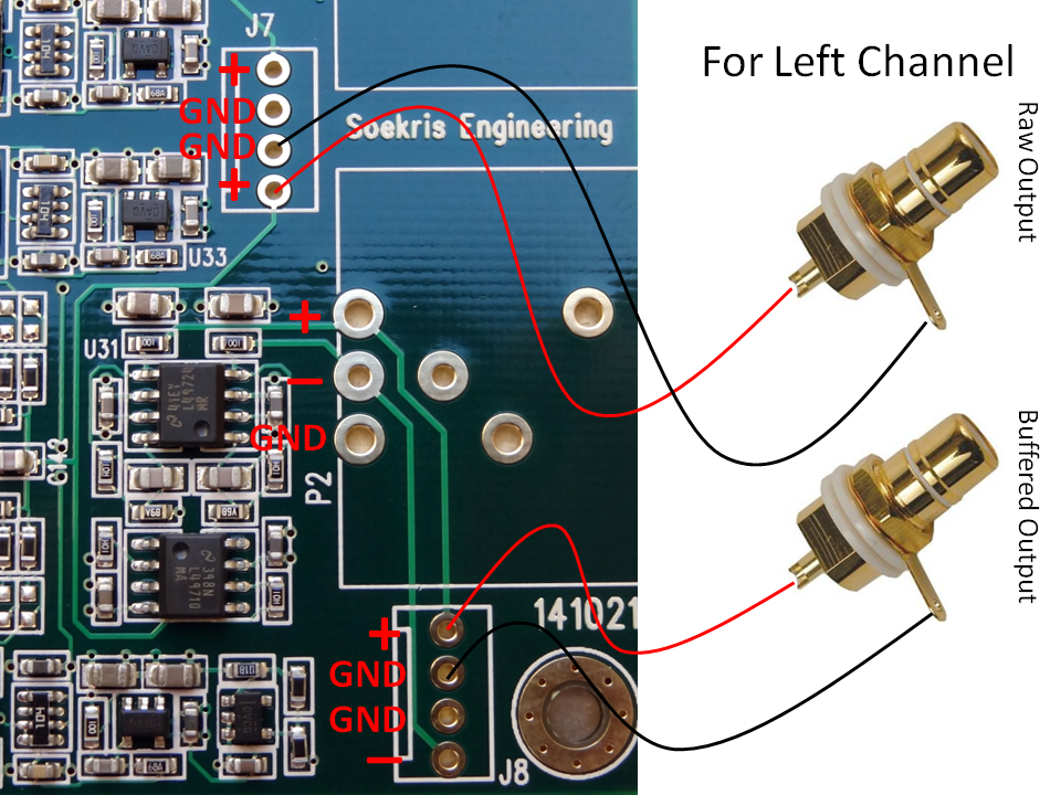
RAW outputs
The raw outputs come straight from the resistor ladder passing just through a low pass RC circuit. Raw outputs provide the cleanest, unprocessed output possible most desired by audio purists. It can be connected directly to an amplifier which typically have high input impedance (>10K ohm).
Note: Balanced offset has been measured to be 2V [link] -need to confirm…
Buffered Outputs
The raw output signal is also routed to a buffered single-ended to balanced signal converter as shown in the following diagram:

Buffered Outputs Balanced Connection

Buffered (and RAW) Outputs Single-ended Connection

The buffered outputs are designed to drive high impedance headphones directly. Here is an example connection to headphone outputs:


I am using a Sennheiser HD-580, with a 300 ohm nominal impedance [link]. Sounds fantastic.
CAUTION: direct connection to an amplifier can result in passing the power on/off pops of the DAC potentially causing damage to the speakers. Follow proper power on/off management: turn the DAC on before turning on the amps and turn the DAC off first before turning off the the amps turn the amps off before turning the DAC off. This power sequence will ensure that the pops will not go through the amplifier circuit to the speakers.
If you are using direct connection (of the buffered output) to a headphone, the pops would be annoying but, at least in my case, they would not damage your headphones.
DIGITAL VOLUME CONTROL
Reference: [link]

The built-in digital volume is enabled with a potentiometer connected as such:
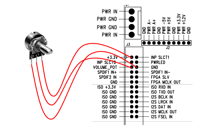
The nominal value for the pot is 10K ohm but any pot would probably work because it is used to set a voltage between 0 V and 3.3V to pin “VOLUME_POT”.
The typical configuration of a potentiometer is the one shown above where the middle pin is the wiper and the end pins are the end connections to the resistance. If you find that your potentiometer does not work as intended you can follow this simple method:
- Find the two “end” pins by measuring the resistance as you move the knob. When then resistance does not change when turning the knob, those are the “end” pins that connect to 3.3V and 0V. The third pin goes to the VOLUME_POT pin
- If you experience that volume decreases when turning the knob clockwise, reverse the connections
If nothing is connected, the volume level defaults to 0 db.
The advantage of using a potentiometer, as compared to using a rotary encoder (which at the moment is not supported anyway), the DAC always starts with the last volume setting.
POWER CONNECTION
The DAC implements several local regulators and therefore it is designed to operate out of a single center-tapped transformer. It can also work with DC input.
The requirements and specifications for the power supply or transformer are as follows [901], [848], [1130]
- DC: +/- 7.5V DC to +/-15V DC; preferable 9-12V DC
- AC: dual secondaries 2x 7-8V AC or center-tapped 0-16V AC
- Power consumption: 2.4V. Thus a 5W transformer is preferred
Transformer Hookup
A favorite transformer is the Hammond 229 series [link] it is a “dual-split bobbin” design with low EMF radiation. It is a step up from the standard low cost transformers.

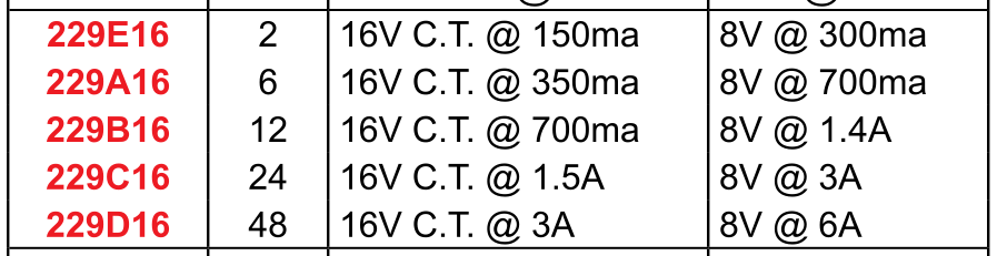
A 229B16 (rated at 12VA)would be an excellent fit with ample power for DAC. It is available at Digikey for about $16 [link]
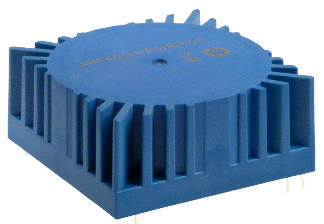
Another option is a low voltage toroidal transformer. A good example is the Amveco 70050 rated at 10VA [link]

The basic hookup of a transformer to the DAC is as follows:

WARNING: AC MAINS voltage can cause death. If you don’t know what you are doing, don’t handle mains voltage.
DC Supply Hookup
The basic supply would be a bipolar +/- 12V supply. A low cost 78xx/79xx-based regulators would be good step up from a transformer-only supply
Note: the on-board bridge rectifier is a fast/soft switching bridge and a low cost DC supply comes with standard diodes/bridge – you may be trading off regulation with increased high frequency noise.
You can find plenty of adjustable supplies on eBay for very little money:
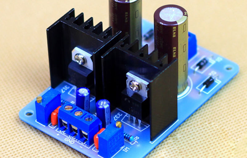
Or better yet, get a higher quality one from diyinhk which includes name-brand components:

The basic hookup is as follows. Notice that if you use a regulated supply, you need to increase the voltage of the transformer. A rule of thumb is to use the same AC voltage as the DC voltage.

Users have reported improvements from using a regulated supply over a transformer only supply [link]
…We started with the DAM as it was, with the Salas BiB (low noise regulated supply). We then unplugged the Salas and hooked up the plain transformer.
The change was immediately obvious. The sound thinned, it became more harsh in the high end. It also lost resolution and detail. Going back to the BiB made all the good qualities come back.
FIRST TIME POWER ON
Turn the power on and measure the voltages through J2 to ensure proper operation:
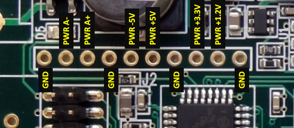
The analog power: PWR A- and PWR A+ depends on your input voltage. For a DC value of 12V you will see approximately 11V because of the voltage drop in the bridge rectifier.
SOFTWARE INTERFACE
Like many modern DACs, the dam1021 has a software interface. You can control the DAC with a micro-controller or a PC, update the firmware and upload custom digital filters.
In most DACs, the communication protocol with the DAC is I2C. In this DAC is serial communication. The dam1021 has two serial interfaces:
- Noise isolated TTL-level serial (not enabled as of this writing)
- RS232 serial (enabled with first release)
Communicating with RS232 Interface
Also check dimdim’s blog which has an excellent writeup on the RS232 interface [link]. Here I document my own experience with the interface.
You need:
- PC serial port
- Or a USB to RS232 interface cable capable of supporting 115,200 baud
- Note: The serial port transceiver on the dam1021 R-2R DAC has power savings enabled, to reduce noise. It needs valid RS-232 level on the RXD line to power up. If your USB-Serial dongle also have power saving then you have a problem. [1176]
- Terminal program
Hardware connection
Connect the RS232 pins to the PC serial port as follows. This is basically a null-modem connection without h/w flow control. You may want to check this informative site on serial communications including RS232 [link]
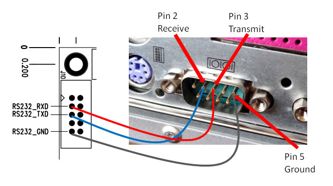
I made a simple 4-feet cable with 2 twisted pairs of cat-5 wires.
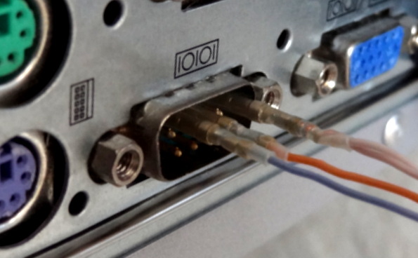
Notice the pins in the board can also be numbered 1-5 counting from the top right in the photo. So pin 2 in the PC serial port goes to pin 3 in the DAC, pin 3 to pin 2 and pin 5 to pin 5.

One can interface with the DAC in two modes:
- Interactive by invoking the “uManager” and using a terminal application
- Non-interactive by sending messages to the DAC through the serial port (with or without a terminal application)
Using Terminal Application (Tera Term)
The terminal program must support xmodem file transfer protocol. Putty is a very popular terminal program but does not support xmodem. “ExtraPutty” is an offshoot of Putty and supports xmodem, but it requires .NET but I didn’t want to download .NET. I ended up selecting “Tera Term”. Check the use of ExtraPutty in dimdim’s post [link]
Download Tera Term from [link]
After downloading and extracting all the files, launch the application “ttermpro”

After launching Tera Term, select “Serial” and select the Port you are using to communicate with the DAC.

Configure the serial communication parameters with:
- Baud rate: 115,200 (This is pretty fast. Use a good, short cable)
- Data bits: 8
- Stop bits: 1
- Parity: none
- Flow control: none
Click on the “Setup” pull-down menu and select “Serial port”

Invoking “uManager” for Interactive Mode
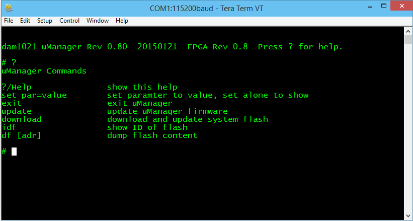
Type “+++” and wait for the DAC to respond (~1 sec). You must enter “+++”, otherwise there will be no response. If you enter anything else, there will also be no response. “+++” invokes the “uManager” enabling interactive communication with the DAC through a terminal window. The DAC also responds to commands sent through the serial interface (more of that later)
The dam1021 will respond with the following screen. Notice the original firmware is “FPGA Rev 0.8”

Typing “?” returns a list of available commands
Updating the firmware
First download the firmware from [1116] and unzip it (it is a “SKR” file):

Type “download” in the terminal window. The DAC will acknowledge your command and wait for you to start the xmodem transfer.
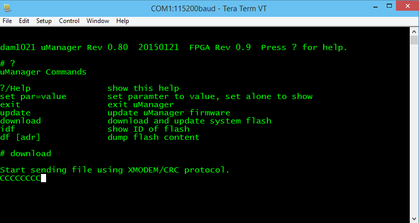
In the “File” pull down menu select “Transfer” -> “Xmodem” -> “Send” and you will see the XMODEM send dialog box. Select the file you downloaded and click “Open”

The file will start transferring and you can see progress in the progress bar.

After completion, [optional – type “exit” in the terminal window] power cycle the DAC. Type “+++” in the terminal window and wait (~1 sec). You will see the following screen. Notice that the firmware version is now 0.9

Non Interactive Commands
You may send commands to the DAC through the terminal application but without invoking the “uManager”. If you are in uManager, type “exit” to exit uManager. The DAC is then ready to receive messages/commands.
UPLOADING DIGITAL FILTERS
Now that we know how to update the firmware, uploading digital filters uses the same procedure. Lots of filters have been crafted by users in the diyaudio filter brewing thread [link]. Filter files ready to be uploaded are binary files. The filter text files cannot be uploaded. They need to be converted to binary format with the “filter tools” provided by Soren [link]
The procedure for uploading a filter file is hereby summarized:
- After invoking the uManager, type “download” in the terminal window. The DAC will acknowledge your command and wait for you to start the xmodem transfer
- In the “File” pull down menu select “Transfer” -> “Xmodem” -> “Send”. You will see the XMODEM send dialog box. Select the filter file you wish to upload and click “Open”
- After completion, power-cycle the DAC. Note: changing the input or changing a track with a different sample rate also triggers reloading of the filters
MASTER CLOCK OUTPUT
Ref: [848]
- I2S MCLK OUT pin: Master clock output: 45.1584 and 49.152 Mhz (which can also be divided)
- I2S FSEL IN pin: Input signal at this pin selects between 45.1584 MHz and 49.152 MHz master clock output
Although not advertised as working with the initial firmware, it has been reported to be fully working as indicated above. [link]
MY OTHER POSTS ON THIS DAC
| TITLE | SUBJECT |
LINK |
DESCRIPTION |
| Soekris dam 1021 R-2R DAC ILLUSTRATED GUIDE | Users Manual | [link] | Users manual for the Soekris DAC. |
| Soekris dam1021 Build | Build Guide | [link] | Details of my initial build of the Soekris DAC. |
| dam1021 R-2R DAC MODs | Mods | [link] | Mods I have performed on the DAC build. |
| dam1021 R2R More Mods | Mods | [link] | Later mods on the DAC build. |
| Digital Filters for Soekris R2R DAC | Digital Filters | [link] | Extensive list of DIY filters from the diyaudio filter brewing forum thread. |
| R2R Benchmark Filters (for now) | Digital Filters | [link] | Latest set of filters developed and shared in the diyaudio filter brewing forum thread. The best filters of the bunch. |
| R-2R DAC For The REST of US | Technical Details | [link] | Introductory post describing the innovations and capabilities implemented in this DAC. |
| The Soekris R-2R DAC: Technical Details | Technical Details | [link] | Additional technical details of the Soekris DAC that were not covered in the post above and collected after I had the DAC on my hands. |
BBB DAC DEVELOPMENTS
As many know, the BeagleBone Black I2S audio implementation is in a way superior to the I2S audio implementation of the Raspberry Pi primarily because the audio clocks can be derived from the on-board 24.576MHz clock and also through off board oscillators through an I/O pin. It its current implementation, the BBB supports the 48KHz family of sample rates with the on-board oscillator and can support the 44.1KHz family of sample rates with an off-board oscillator.
The current method of generating the clocks for digital audio in the Raspberry Pi are far from perfect. The best clocks are obtained by integer division of the on-board 19.2 MHz clock and works for 48K and 96K sample rates and only if the DAC can accept 40fs or 80fs. For anything else, the clocks are derived from the 500MHz PLL through fractional division as explained above. It has been reported that the 500MHz clock itself is derived from the on-board 19.2MHz clock through a clock multiplier.
Even with a “superior” audio clock implementation, I2S DAC development for the BBB has been painfully lagging that of the Raspberry Pi (so painful that there are no products shipping). The reason is because that there is a lot, lot more community development in the Pi than the Beagle. The RPi has just shipped its 5 millionth device [link] whereas the BBB has only shipped about 220K devices [link].
No longer.
TWISTEDPAIR AUDIO
Twistedpair Audio has been busy designing and testing external components to allow the BBB access to lower jitter off-board oscillators and data reclocking for ultimate I2S signal fidelity. These boards are almost ready for general sale [link]
Update 3/26/15: they are available for sale [link], and pretty reasonably priced given the components. (The store says “introductory pricing” though)
The mockup photo below shows (from right to left) BBB, “Hermes”, “Cronus”, and Buffalo III DAC. The board on the top is the Hermes board for the Amanero interface. With Hermes-Cronus, Amanero can use better off-board clocks if so desired.

These links explain the functionality of these boards [link], [link]
- BBB as the source of I2S/DSD digital audio, it needs external clocks in order to support all sample rates
- Hermes as the two-way signal isolator (clock signal into BBB, audio data signals out of BBB, and I2C in-out) and I2S/DSD switch. Hermes also has connections for a volume pot, push buttons, etc. that interfaces to I/O pins in the BBB -more details below (priced at $40 or $16 for the board only)
- Cronus is the clock board which can accommodate two clocks: one for 44.1KHz sample rate family and one for 48kHz sample rate family. Cronus also provides data realigning of the I2S signals (as opposed to FIFO reclocking) – more details below. (Priced at $50)
- Clock modules. The clock modules are available separately from the Cronus board with a choice of frequencies and are priced at $35 each. You need two.
- Total is $160 for Hermes+Cronus+Clocks. You don’t really need the Hermes if all you are interested in are the clocks, so the minimum investment is $120
Here is a photo of the updated Hermes board (the interface/isolator board between BBB and Cronus)

- Provides isolation for audio signals with 1 -8 channels of PCM – 1 – 4 channels of DSD output
- Provides I2C isolation
- SPDIF output is possible.
- Lots of headers: for Switches/Rotary encoder and drivers for indicator LEDs; USART header, ADC header for analog control; headers for external power/reset switches.
- Prototyping area (for fun!)
- Provision for backup battery to protect the BBB on shutdown by providing a soft shutdown(self regulating battery not included in the kit – but very easy/cheap to obtain).
Here is a photo of the updated Cronus

- Ultra low noise low impedance power supply for clocks (adm7150)
- A clock selection multiplexer to switch between 44.1 and 48Khz time bases (this means the source must output a clock selection signal). The clocks are isolated from each-other and the rest of the circuit by utilizing L/C filtering
- A selectable/bypassable ultra low phase noise clock divider to supply 1:2 or 1:4 clocks to a source
- A synchronous reclocker that re-clocks the audio from the source back to the master clock. This brings all signals back into alignment with the actual master clock regardless of source jitter. Uses Potato Semi flip-flops. To learn more, here is my crude attempt at reclocking [link]
- SMA and uFL connectors for external clock signals (both in or out), uFL connectors for PCM/DSD output.
IQAUDIO
IQAudio’s main products to date are audio boards for the Raspberry Pi. As I wrote here [link] their DAC board is one of my favorite for the Raspberry Pi. The DAC boards for the RPi are also very popular, often sold out at the Tindie store [link]
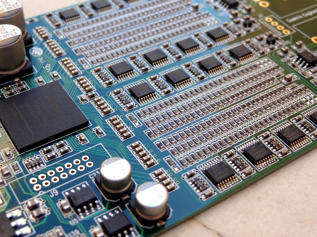
The IQAudio BBB DAC is aimed at a full I2S DAC solution for the Beagle. A photo of a prototype is shown below.As can be seen in the photo, there are no external clocks that can be fed to the BBB. Normally a DAC operates in Slave Mode. The DAC locks to the master clock or bit clock of the source and receives the data from the source device. In the IQAudio solution, the DAC instead is running in Master mode. The DAC generates the appropriate bit-clock frequencies in accordance to the sample rate of the track being played and it “pulls” the data from the BBB. You may follow its development here [link].
According the manufacturer, the board will be available in May at a target price of $45-$60. Please send your queries and comments to IQaudio at Gordon@iqaudio.com.
Notice also the I2S headers. Possibly you can use this board and tap the I2S signals and use them for another DAC board.

Comparing with the RPi DAC which is shown below, it seems the BBB DAC uses almost the same components. The innovations are in software: drivers in the BBB side and firmware to setup and control the DAC chip.

There is also an advantage of buying a product from iQAudio (and other similar companies such as HifiBerry) in that they invest in software development (drivers) and provide many ready-to-run software distributions for your embedded computer.
ACKO SUPERCAPE
Acko is also planning to release a BBB cape that is derived from their current clock/isolator board which is already a working solution for the BBB. A nice photo from this post [1828]:

The “supercape” adds battery management to the capabilities of the current clock board in an integrated package. It will provide:
- UPS kicks in when external power is removed. On-board PWR_MON will continue to power the BBB (~1hr) or options to safely shutdown BBB immediately. Same shutdown action if battery level goes below operational level [1088]
- High Speed Galvanic Isolation with -Synchronous or Asynchronous re-clocking.capability
- Ultra-low jitter Dual Synchronous Audio Clock (98.304MHz/90.3168MHz or 49.152MHz/45.1584MHz options) – Master Clock
- All buffered outputs with high drive capability
- GHz rated switching components
The following diagrams show the work-in-progress for this cape, starting with adding a USP and interface for the BBB and the clock board to the current configuration of a fully integrated cape.
From: [1088]

[1332]

From [1587]:

SOEKRIS dam1021 DAC
The Soekris R2R DAC supports the BBB in synchronous slave mode by providing the required master clock frequency as selected by the BBB. BBB is in master mode, but the DAC provides the clock
- I2S MCLK OUT pin: Master clock output: 45.1584 and 49.152 Mhz (which can also be divided)
- I2S FSEL IN pin: Input signal at this pin selects between 45.1584 MHz and 49.152 MHz master clock output
It works in a similar fashion as the TwistedPair and Acko solutions but it has been incorporated into the DAC.
I have yet to experiment with it myself but has been reported to work: [link]

Latest Comments